Emtech ZM-2 Antenna Tuner Kit

(Click on any picture to get larger, high-resolution version)
built by Monty Northrup, N5ESE
built by Monty Northrup, N5ESE
| NOTE: 'N5FC' is my former call. This project was constructed while that call was valid, and you may observe references to it. |
The Emtech ZM-2 Antenna Tuner is a nifty little portable transmatch for QRP (low power). It utilizes the well-known Z-match circuit, which is especially useful for balanced antennas (like dipoles and loops). Since it's a very inexpensive kit (around $50), and because there's an constant clatter about it on the QRP-L mail list, and because I travel a lot and need the miniature equipment, I figured it would be worth investigating.
Construction Notes
This is a pretty easy project to put together. The kit has about 20 parts. Give yourself half-a-Saturday. The instructions come printed on 10 letter-sized sheets, and include step-by-step assembly. There are two transformers to wind on toroid cores. The first (and larger one) is shown below. The instructions contain pretty good black-and-white drawings, but because they have so many taps, it would be pretty easy to get confused. A color picture might help:

T2, the SWR-bridge auto-transformer, the smaller toroid, is a little simpler to wind, but no drawing is provided. Still, the word-description is adequate, and no problems were encountered winding this coil. It can be seen in the internal views (shown below) as the bright-green toroid winding.
All the components are mounted on the single (and rather thin) aluminum panel. The kit-buyer must drill this panel, and a template is provided for locating holes. Be sure to use pilot drills and go slowly, because using a standard electric hand drill and high-speed bits has the potential to really mess up this front panel. But, hey! That's what homebrewing is all about. I used a "step-drill" (sometimes called a "Unibit") mounted on a drill press and using a wood backing; this method gave me clean holes. Emtech provides a sticky-back laser-printed front panel label, which you can place on the drilled aluminum panel to get a pretty nice visual effect. I put some transparent self-adhesive laminate over mine, to keep it from getting dirty. After placing the label, you use an hobby knife to cut holes in the paper to match the holes you drilled in the panel.
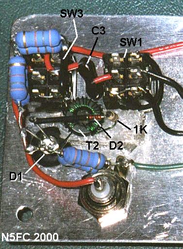
After drilling the front panel and placing the label, you mount all the obvious parts onto the panel (LED, switches, capacitors, connectors). All the controls and connectors mount on this one panel, and during operation, it can feel a little crowded, but it seems to work. Once you've mounted the parts onto the panel, you flip it over and begin melting solder. The front panel components are used as mounting points for nearly everything, but the diode and resistor must be mounted 3-D style (mid-air solder joints). This is kinda flimsy, but the components don't have a lot of mass, and it works. If you don't feel good about it, you may want to add some kind of standoff terminals to make the connections more solid. Here's a picture of the construction just before mounting the larger transformer T1:
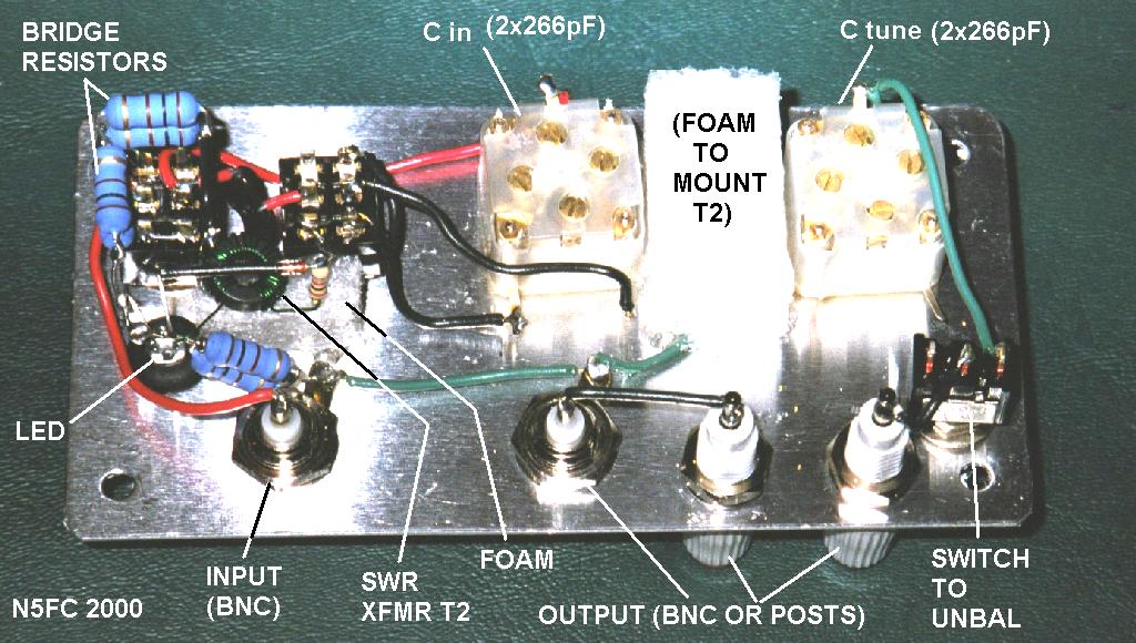
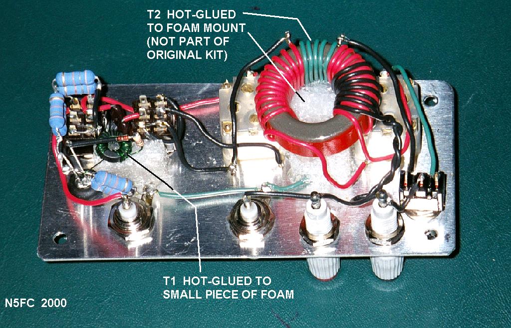
One thing to notice is that I've placed small foam blocks (from scrap packing material) to mount the transformers so that they'll stay in place. Here, we used the XYL's hot-glue gun to stick these down (and we'll do the same to mount the toroids). Here's another detail of the input circuit, showing the 3-D components and the SWR transformer T2 mounted on a little piece of foam:
Finally, here's a view of the completed assembly (internal), with T1 hot-glued in place. Nothing left here but to drop the entire thing into the black-plastic enclosure, and hook it up for a test.
Testing and Tuneup
For testing, I'll place a standard SWR meter between the transmitter and the new ZM-2 tuner, so I can see how well this little baby does its job. I won't trust it until I see for myself that it's working.
The first antenna I tried was my old reliable twinlead-fed 40 Meter dipole. I use this antenna on all bands 40 through 10, tuning it with an MFJ-971 T-match. I transferred the twinlead to the binding posts of the ZM-2, and proceeded to tune-'er-up. First, I switch to "TUNE". This places the 50-ohm bridge circuit between the transmitter and the antenna. Then, I listen. I twist both knobs for maximum noise, easily heard. Then I key the Ten-Tec Scout (5 watts, of course). Hey! The LED lights! Twist two knobs slightly, and 5 seconds later I have my null, as indicated by the dimming LED. It dims to black, easily visble. Wow! that was way too easy, and much easier than the T-match circuits I've used. Let's make a contact. Whoops, I forgot to switch from "TUNE" to "OPERATE" (not much power gets to the antenna in "TUNE"). Hey, switched to "OPERATE", and it works!
We then tested the unit on the remaining bands (30, 20, 15, 10). On these bands, the null was not to black; nearly so on some, barely noticeable on others. But in all cases, the null produced a 1:1 SWR, as measured by the "cheat" SWR Meter. After making a contact on each band, we declared the ZM-2 usable.
Eventually, we tested the ZM-2 on several other antennas. It works quite well on my Notebook Antenna and DCTL Antenna (both balanced antennas). I was unable to tune the Notebook on 10 meters, which I found somewhat odd. But, that's tuners for you! (I've never found a tuner that worked well for every antenna and all bands).
I have not yet tried it with an end-fed antenna. A switch is provided for grounding one side of the T1 output link, so that the tuner can be used with an unbalanced antenna. It should work fine for a quarter-wave end-fed, but may not have enough range for a half-wave end-fed wire. (Anybody out there ever try that?)
Summary, and My Impressions
This one's a keeper! I find myself reaching for this tuner anytime I have a notion to experiment with antennas (which is often). It works well, giving a good match to most every antenna. I've not tried it on 80 meters, and I only found one antenna on 10 meters that refused to match, but all other bands worked great. The LED doesn't always go out when matched, and sometimes I wonder if I'm getting a good match. But after adjusting the LED for minimum, and checking the SWR with an independent meter, I'm convinced it's working. Sometimes, the null is so narrow that it's really easy to miss it altogether, and very hard to set it to minimum. These behaviors are likely antenna-dependent, and maybe band -dependent. I wonder if a variable resistor in series with the LED might allow the null to be more appparent during tuning? Occasionally, I'll forget that I have to switch from "Tune" to "Operate", and wonder why I'm getting no answers to my calls (although, once I did get an answer in "TUNE" mode). Oh, well...
It's nice having a balanced tuner without having to worry about balun mis-matches and losses. And the small size and weight make it just about perfect for travel and portable QRP. Plus, this thing is just doggoned cute!
73,
Monty N5ESE
dit dididit dit