N5ESE's Notebook Antenna

A Low -Power Indoor Portable HF Antenna
by Monty Northrup, N5ESE

A Low -Power Indoor Portable HF Antenna
by Monty Northrup, N5ESE
| NOTE: 'N5FC' is my former call. This project was constructed while that call was valid, and you may observe references to it. |
| Antenna Disclaimer |
|
Right from the top of this page, I'm going to say that I'm an antenna experimenter, not an antenna expert. Purely seat-of-the-pants. In fact, you might even say I'm an antenna cynic. I know how to use antenna analysis tools, and I often do, but I take them with a serious grain of salt. I've found, in my 35 years of experimenting, that some antennas work much better than predicted, and some work much worse (and that they're more likely to work worse than better HI HI ). Still, I find experimenting to be one of those true joys of amateur radio, and I encourage all of you to just "try it out" for yourself, and for Pete's sake, don't take my word for it (nor my explanations).
I find that most technical people do this (and I am no exception): upon observing a phenomenon, we make up an explanation for why we got our observed results. We base this explanation on the current subset of knowledge that we've gained from education and experimentation and folklore, and we're not likely to look for another explanation until we have another experience which forces us to expand or revise our previous explanation. Please realize this is the case with me, also, and then enjoy the web page. |
(Pictures and Diagrams follow the narratives)
On this page, we'll describe the multiband Notebook Antenna, so called because the entire antenna will fit easily inside a 1" thick 3-ring binder. The antenna is intended for indoor use, with low power (50 Watts or less). It can be easily set up (or re-packed) in minutes. When used with your favorite balanced antenna tuner, it will work on any band from 40 through 10 meters.
Background
I travel on business way more than I want to. Besides eating at new restaurants, there's not a lot of reward in 12-to-16-hour workdays (which is what always seems to happen to me when I travel). Hamming from the hotel room can be a welcome distraction which helps diminish the sense of isolation one gets while on travel alone. For this reason, I'm always looking for antennas that can be thrown up quickly - indoors, of course - yet still manage to get some RF out into the ether.
To this end, then, I've tried a number of antennas for both receiving and transmitting. Here, I'll present one of the more compact and unusual ones.
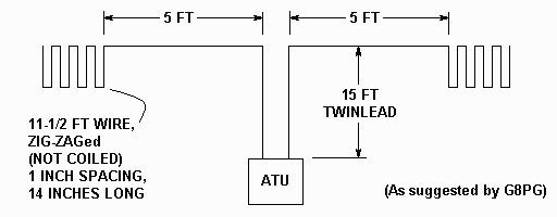
In the Fall 1990 edition of SPRAT (Issue 64), Gus Taylor (G8PG) , expanding on material presented by G2MQ, described a 12-foot, 7- band wire doublet. A rough sketch is shown below. In the article, he suggested that one could raise the efficiency of a short antenna by using the entire (1/4-wave) length of wire on each leg, but forming the ends into a "non-inductive" end-loaded assembly. He claimed that such a winding had been found to increase the radiation resistance of a short antenna. And that implies higher antenna efficiency.

Antenna Efficiency
Allow me a moment of digression to explain that statement. Radiating efficiency aside for the moment, it should be understood that the sigificantly short antenna (as we are considering here) will probably never receive as well as a full sized antenna, simply because it has reduced "aperture" (meaning it doesn't occupy as much physical space and so cannot extract as much energy from the available space). We'll overlook the shortcomings of small antennas as receiving devices, since modern-day receivers usually have sufficient reserve gain to accommodate the needs of most portable operations. Having said this, however, we can use efficiency as a measure of the ability of the antenna to inject energy into the available space, and make the relative task of increasing efficiency a worthy goal for improving antenna performance.
The first problem one has with short antennas is getting the power from the transmitter to the antenna. An antenna tuner is the most common (and probably most expeditious) way to accomplish that. In a balanced antenna such as this, getting a good match is not too hard. Let's say, for example that you operate QRP (like me). The transmitter generates 5 Watts into a 50 ohm load. You adjust your transmatch (antenna tuner, or ATU) to get a 1-to-1 SWR at the transmitter. If you consider the feedline to be part of the antenna (it usually is, in a portable), then once you have your match, you have most of the power getting to the antenna. That power has to go somewhere. In a full-sized antenna, without obstructions, over a good ground, you'll get 95-99% of that power radiated. That's good efficiency.
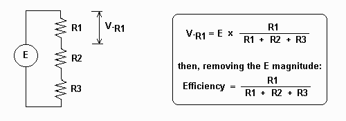
Antenna efficiency has been described in terms of radiation and loss resistances, and I find it useful to think in these terms. It's kind of like voltage in a bank of series resistors. Remember the formula? If we have three resistors R1, R2, and R3 in series, and connected to a voltage source E, the voltage across the first resistor is expressed as shown below. If you throw away the voltage magnitude what remains is the percentage of source voltage E that will appear across R1.

NOTE: Please don't write to me complaining that the formula fails to address loss 'X' or condition 'Y', or that it isn't a mathematically correct model of antenna behavior... that is not our purpose here. Rather, we intend this model to serve as an analogue for conceptualizing how these parameters affect radiating efficiency. And to that end, this model works well (my apologies to the academics)
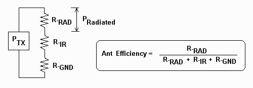
Well, thinking about antennas again, if we use this model, R-RAD (formerly R1) represents the Radiation Resistance, i.e., the part that's actually going to do the work and radiate into space. R-IR (formerly, R2) represents the IR losses, i.e., the wire or copper losses (this really IS resistance). And R-GND (formerly R3) represents ground losses. Now let's see our formula:

Notice a few things about the formula:
But short wire antennas present a serious problem for radiation efficiency. A doublet's radiation resistance decreases as it shortens. For example, a 40 Meter doublet with 33 foot long legs would show a radiation resistance of around 70 ohms; shorten that to 5 or 6 feet, and the radiation resistance becomes 2 or 5 ohms, or less... suddenly. for the same ground and wire losses, we're talking about radiation efficiencies of between 2 and 25%. Yikes! Now, for our 5-watt transmitter, we're only radiating between 100 milliwatts and 1 watt.
As anyone knows who has tried to use a short or otherwise down-sized antenna, all this translates into poor performance. As we can see (by plugging in the numbers), if we have to deal with a short antenna, we have three choices for improving antenna efficiency:
Lowering the copper losses in a portable situation can also be inconvenient. Yes, you could use 12 guage wire, but it's weighty and cumbersome to handle. And if the antenna has to be portable, connectors may rely on mechanical joints instead of solder joints, leading to more losses and lower efficiency. Still, this is an area that can be easily controlled, and often improved.
That leaves us with radiation resistance... huh? you say... There are a few things that folks (smarter than me) have discovered that can raise radiation resistance in shortened antennas. Capacity hats are one, usually at the end of the radiator. The technique described here is another. While I can't vouch for the reasons suggested by the author as to why this improves efficiency, he claims (quoting):
"The method was simple: to whatever length of wire could be erected, was added a further quarter wavelength of wire, wound in a series of narrow U-shapes... Adding this non-inductive loading... the radiation resistance of the wire was increased, sometimes dramatically. For example, at 1.8 MHz the radiation resistance of a 15 foot wire should be increased by a factor of 14, and that of a 66 foot wire by a factor of 4."
A Practical Antenna
Using these thoughts as the foundation for an antenna design, I endeavored to come up with something both practical and usable for operating QRP from a hotel room. Whips have been used but are notoriously inefficient, and certainly won't fit in my suitcase. Wire loops have also been tried, and are either hard to tune or very inefficient when less than a full wave long (there are exceptions, like the DCTL antenna, which I describe here). Magnetic loops are very, very efficient, but are hard to fabricate, expensive commercially, and cumbersome to transport. I wanted an antenna that was very portable (i.e., fit in my briefcase), easy to set-up and take-down, and reasonably efficient (or at least, relatively so, compared to other equally portable antennas). The Notebook Antenna is the result of my efforts.
Some time ago, I found that hobby stores (like Hobby Lobby and Michaels) carry adhesive-backed copper-tape. The 1/4 inch-wide tape is approximately equivalent to AWG 25 wire (in cross-section), and two in parallel equal about AWG 22. This would be quite usuable (and believe it or not, quite solderable). Now, instead of using wire and boxes to "wind" the non-inductive end-loaded parts of the antenna, I'll use an 8-1/2 x 11 inch (letter-sized) transparency, and lay the tape down, zig-zagging on both sides (in parallel). I'll make two, of course (one for each leg of the doublet), and I'll punch holes for a three-ring binder. The transparency might easily tear if excess force is applied, so we'll place an eyelet on the top-inside corner (the kind found in cloth stores), and thread our support rope and antenna wire into this eyelet. The support rope (a small diameter nylon string) will pass through the transparency's 3-ring binder holes, to keep it in place, but the eyelet will take all the strain. For the antenna wire, we'll use AWG 16 wire (although AWG 18 would work as well), and we'll feed the antenna with 15 feet of low-loss twinlead, as suggested by the author. The pictures below will tell the story far better than I can in words. I suggest you use a 1/4-wave counterpoise (at your antenna tuner ground) when using the antenna on 30 or 40 meters; none should be required on 20 through 10 meters.
Construction
Materials:
Assembly
1. Using the template provided (or working with your own pattern):
Operation
Installation and tune-up takes place as follows:
Results, and My Impressions
My first QSO from central Texas, with the antenna hanging from coffee hooks placed in the ceiling of my first floor bedroom, and using 5 watts on 15 meters, was with Brian VE3ADX, in Ontario, who gave me a 549. We QSO'd for 8 minutes with no problems. My second QSO was on 20 meters, again 5 watts, with Rusty KC4ZPB, in Tennessee, who was also QRP, and who gave me a 559. We QSO'd for nearly half an hour. The antenna is a little more susceptable to power-line radiated noise (than is an outside dipole), and this can be problematic in some locations. While received signals were down about 1-1/2 to 2 S-units (as compared to the full-sized outdoor dipole), the power line hash was not similarly reduced. Of course, it was indoors (and hence closer to power lines). Efficiency? Who knows... but IT WORKS! ...73, Monty N5ESE
Update: Sverre, LA3ZA, is kind enough to share his very encouraging comments and experiences on the Notebook Antenna (click -here-)
73,
Monty N5ESE
dit dididit dit