N5ESE's Look at the RFD (Resonant Feedline Dipole)
| NOTE: 'N5FC' is my former call. This project was constructed while that call was valid, and you may observe references to it. |
| Antenna Disclaimer |
|
Right from the top of this page, I'm going to say that I'm an antenna experimenter, not an antenna expert. Purely seat-of-the-pants. In fact, you might even say I'm an antenna cynic. I know how to use antenna analysis tools, and I often do, but I take them with a serious grain of salt. I've found, in my 35 years of experimenting, that some antennas work much better than predicted, and some work much worse (and that they're more likely to work worse than better HI HI ). Still, I find experimenting to be one of those true joys of amateur radio, and I encourage all of you to just "try it out" for yourself, and for Pete's sake, don't take my word for it (nor my explanations).
I find that most technical people do this (and I am no exception): upon observing a phenomenon, we make up an explanation for why we got our observed results. We base this explanation on the current subset of knowledge that we've gained from education and experimentation and folklore, and we're not likely to look for another explanation until we have another experience which forces us to expand or revise our previous explanation. Please realize this is the case with me, also, and then enjoy the web page. If you really want to know how it works - without my ignorant rantings getting in the way of a thorough understanding - click -here- |
The purpose of this page is to document my personal experiences with the end-fed dipole based on the concepts presented by J. Taylor in an article titled "RFD-1 and RFD-2: Resonant Feed-Line Dipoles," in QST. August 1991. I'll leave it to that reference to expound on antenna theory, and I'll focus on my own construction methods and observations.
The Resonant Feedline Dipole (RFD) appealed to me because of my interest in portable antennas for QRP field ops. If you've ever tried to hang a center-fed dipole or doublet in a forest or trees, you'll understand exactly why an end-fed dipole would appeal. The simplest field antenna involves tossing a weighted line over the nearest high tree, pulling the wire up as high as it will go, and feeding it from the end. Wouldn't it be nice to have the performance of a conventional dipole, with the ease of installing an end-fed wire, and without having to deal with the center-feed? That's the "claim-to-fame" for the RFD. To what extent it measures up, we'll leave for the observations below. Understand, however, that the RFD-1 (described here) is a single-band antenna (though it may work on the third harmonic), unlike the center-fed doublet, which will often tune all-bands (with an antenna tuner and a judicious choice of feedline).
NOTE: You might also look at the site of KO4WX, and look for his online article titled "Revisiting the Resonant Feedline Dipole" in which Mike Boatright describes yet another approach to constructing the RFD.
Construction
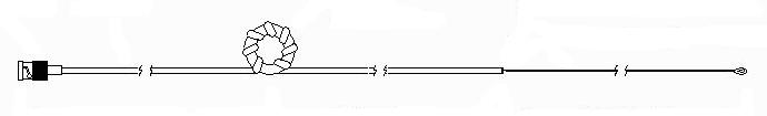
Here's a basic diagram of the RFD:
In the above sketch, please note that the active (hopefully, radiating) portion of the antenna (on the right) consists of an electrical half-wavelength. Like a dipole, the RF current maximum is at the center of the half-wavelength, making it a "dipole". The "center" (or rather, center-equivalent, if we can call it that) is the point where the coax ends and the center conductor continues to the right. We do indeed have a feedline connected to this point (our feedline coax), but we require the choke at 1/4-wave to the left of the "center" to force the RF to flow correctly on the outside of the feedline, so that it acts like a dipole. The "choke" is the element that peforms this magic for us. In this context, a "choke" means an electrical element that serves to "choke" common mode RF at that point. That is, the choke looks like a very high impedance to the RF currents reflected from the center discontinuity (where the feedline abruptly ends in an open-circuit), and traveling down the outside braid of the coax. The extent to which the choke element does its job -- and its location electrically from the dipole "center" -- determines how well the RFD works, and what impedance will be seen by the rest of the feedline, extending to the left of the choke. Nominally, if all goes well, the impedance seen by the feedline will be near 50-ohms (and this is the characteristic impedance of the feedline we should use in construction). This makes the RFD suitable for readily available coax types RG-174, RG-188, RG-58, RG-8M, and RG-8 (though RG-8 is a little stout for a portable antenna).
There are three important points to be emphasized here, to avoid confusion. First, there is physically only one single contiguous feedline, and it extends from the connector on the left, through the choke, to the "center" discontinuity. Second, the feedline may be any random length leftward from the choke (assuming we have a good choke and locate it correctly). Third, the coax shield is open at the "center" discontinuity; i.e., it is NOT shorted to the center conductor or to the wire extending rightward.
As illustrated above, three basic types of choke constructions might work for us: the toroid-choke, the coil-choke, and the bead-choke. The toroid-choke consists of a medium-to-large-sized ferrite toroid, with several turns of the feedline around it. Because of the difficulty of forming turns of coax around a toroid, this method is probably only practical for small-diameter, flexible coax, like RG-174. The coil-choke is the choice used by the original designer, J. Taylor. It consists of a single-layer solenoidal winding, close-wound (NOT scramble-wound). The bead-choke consists of several adjacent ferrite beads placed on the outside of the coax (usually 15-25).
In the case of the toroid-choke and coil-choke, there will be distributed capacitance as a result of the coaxial windings, one turn to the next. There will also be an inherent additional inductance in the inner conductor of the coax, as a result of the turns. While one may consider these to be "stray", parasitic, or unwanted reactances, Taylor points out that these may actually contribute toward forming a parallel-resonant circuit at the choke-point, thus improving the "choking" effect (which is essential). I did not investigate this aspect of the choke, although the original article suggested ways to predict and use it when using the coil-choke construction.
Experiments and Observations
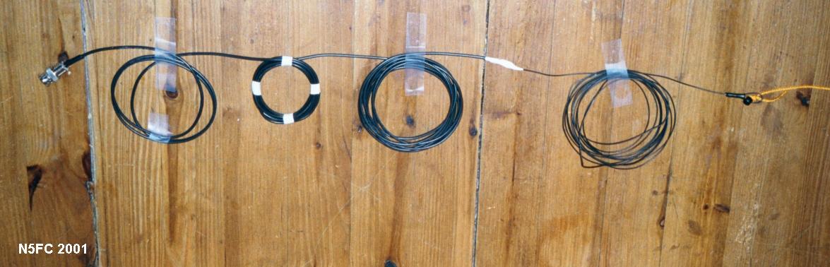
The image above is the first version I built. This one used RG-174 miniature 50-ohm coax in it's construction, and was constructed for the 15 Meter CW band. The feedline was terminated in a BNC plug, which you can see loosely coiled for storage at the left. I allowed about 3 feet for "feedline" (to the left of the choke). The "choke", which is the second coil of wire from the left (with 4 pieces of white tape), consisted of 8 turns of the feedline coax, with a diameter of roughly 3-1/2 inches. This was scramble-would (which turned out to be a less-than-optimal). From there, you can see approximately 11 feet of the remaining feedline coax (extending rightward from the choke). At that point, I cut the shield back, leaving about an inch and a half of center conductor extending out. I heat-shrank tubing over the outer shield cut, to seal it and prevent shorts with the center conductor. I then connected and soldered 11.1 feet of hookup wire (actually superflex insulated antenna wire, AWG 26) to the center conductor. For mechanical strength and electrical insulation, I folded this wire back against the insulated feedline, and heat-shrank more tubing over the entire joint (electrical tape would work as well). Then I formed a small loop at the end of the hookup wire for pulling the antenna up into the trees (or whatever its supporting structure might be).
I was eager to test the antenna. I hauled it up from my regular base-station 33 foot mast, until it was suspended like a sloper, with the bottom end (BNC plug) in my hand, connected to the antenna analyzer. I surmised that I could "roll" the choke back and forth enough to achieve the lowest SWR on my MFJ Anetnna analyzer, but the lowest I could achieve was about 2.5:1.
The first mistake I encountered in construction was in calculating the length of the 1/4-wave feedline between the "center" discontinuity and the choke. I assumed that I should apply the velocity-factor of the coax (roughly, 78%) to determine the physical length of the quarter-wave section. However, I soon discovered empirically, that the RF currents being choked flow only on the outside of the coax, and are subject only to the dielectric effects of the outside insulation, much like the effect of using insulated hookup wire versus uninsulated wire. Thus, instead of a velocity factor of 78%, expect something in the range of 95%. So the correct distance from center to choke ended up being near 11 feet (246 * 0.95 / 21.060 = 11.096 ft)
The second mistake was scramble-winding the choke. Apparently, the extra distributed capacitance served to undermine the choke's effectiveness. I then went and found a piece of 4-inch diameter cardboard shipping tube, and re-formed the choke into side-by-side winding (solenoid winding). After doing so, I was able to achieve a 1.7:1 SWR. The distance (from the "center" to the choke) turned out to be somewhere within a foot of the predicted 11 feet (but closer to 12).
I tried this antenna on several outings to my daughter's house in Waco, with the antenna hoisted about 20 feet at the far end, and feeding directly into a NORCAL BLT tuner, then via short coax to my TenTec 1315 CW Transceiver at 3 watts. Results were disappointing. While I did not do a side-by-side comparison, reports were consistently down from previous experiences with a short random-length wire and the same antenna. Still, I was able to make QSOs, though often with S3 and S4 reports, and rarely would a CQ bring a response.
I speculated that the RG-174 was extremely lossy at this frequency, so I went about creating several other versions. The first was a 30-Meter version using the same construction technique. An image is shown below (but the image shows a scramble-woulnd choke, later changed tto solenoid-wound):
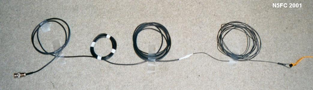
For this version, I continued to use RG174, but increased the choke turns to 12. On initial testing, this one did not behave as I expected. With the outer "leg" cut to 23.1 feet (246 * .95 / 10.110), and expecting the distance from "center" to choke to be just a little more than that, I had to wind the choke all the way out to the BNC connector (about 30 feet choke-to-center) before I fell as low as 2.2:1 SWR. Had I more feedline, I might have gotten it a little lower. Still, I tried this again at my daughter's house, using the BLT tuner and TenTec 1330 transceiver at 4 watts, and got results very similar to those encountered on 15 Meters, i.e., disappointing signal reports.
It was now time to try a different choke. Re-using my previous RG-174, 30-meter antenna, I dismantled it to install a toroid-choke. I wound 7 turns as tightly as I could onto two stacked FT114-43 ferrite cores. Because it would be fairly difficult to move a core like this up and down the feedline, I decided to place it at the predicted spot (0.95 * 1/4- wavelength from "center") and take whatever I got. What I got was a 2.5:1 SWR, and about 12 feet of "leftover" feedline (which used to be in the coil-choke).
This was about the time we would be vacationing at Port Aransason the Gulf Coast of Texas, and I took the opportunity to deploy this version on the beach for daytime ops. Here's the antenna, deployed:
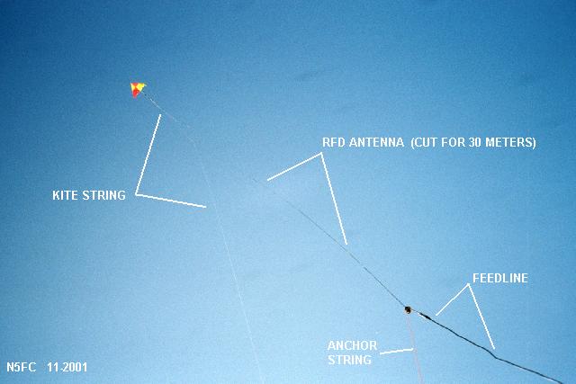
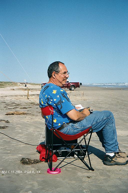
I procured my XYL's favorite kite to hoist the RFD antenna, and used some stouter nylon twine to anchor it into the beach, tying the twine to the choke to make sure the antenna wouldn't get away. The kite raised it to near-vertical, with the BNC end again going to the Emtech ZM-2 tuner and the TenTec 1315 at 3 watts. Results were tolerable (in other words, I managed QSOs), but at least one S unit (and maybe closer to two) down from a 33 foot vertical wire and counterpoise I used the following day. Here I am in QSO in the beach:
The next thing to try, because it would allow larger, less lossy coax, and allow more readily adjusting the position of the choke, was a bead-choke. For this, I constructed a 15-Meter version using RG-58 cable, with 25 each FT50-43 ferrite beads for a choke. Here's a picture of the completed antenna, loosely coiled for display:
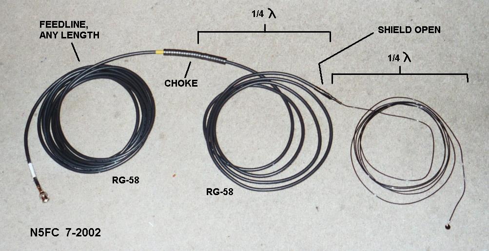
I was quite hopeful for this version; in fact, I was so sure it would work, that I built versions for 40, 30, 20, and 15 before even testing them. But once again, I was disappointed in the results. In this case, for all versions, I could not find a location where the SWR dropped below 2.5:1, and the point at which it dropped to it's lowest SWR was quite ill-defined, being 100 - 120% of the nominal quarter wavelength (choke-to-center). At this point, I was sufficiently discouraged that I gave away my RFD's to members of the Austin QRP club, in hopes that one of them might figure out a way to make them work better.
Conclusions
While experimenting with antennas is always fun (and this was no exception), I cannot recommend these antenna designs for portable QRP use. This is not to say you won't get a signal out. On one field trip to a mountain top in the mountains of norther New Mexico, perched on an outcropping at 8700 feet, with the 15 Mter RG-174 version of the RFD suspended as a sloper to a fir tree, I was able to QSO a JA station for 15 minutes, using a TenTec 1315 transceiver at two watts on internal batteries. Here's a picture of that deployment:
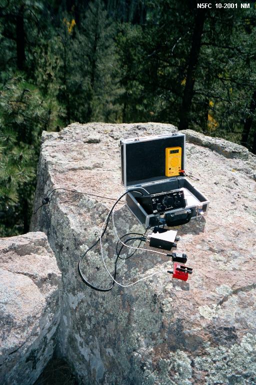
(click on the image above to see a larger image)
You can see the toroid-wound choke laying on the outcropping. Notice, I'm still using an antenna tuner (the NorCal BLT). But recall, one of the advantages of the RFD was suposed to be not needing one. I suspect my sucess had more to do with the location than the antenna. Still, it did work! And what a view!
Based on my experiments, if an end-fed antenna is called for, a random length of wire and a counterpoise (along with a suitable antenna tuner) will probably serve you better. Certainly, this antenna (even though it's called a "dipole") does not perform as well as a center-fed dipole in the same configuration, nor as well as an end-fed half-wave likewise configured. Sorry, Charlie!
73,
Monty N5ESE
dit dididit dit