N5ESE's Low Battery Warning Gizmo
(click on any picture to see larger version)
(click on any picture to see larger version)
| NOTE: 'N5FC' is my former call. This project was constructed while that call was valid, and you may observe references to it. |
When I built the KD1JV AT-Sprint (a 3-band, 5-watt CW Transceiver with DDS VFO) into an Altoids tin, I wanted a battery pack that was worthy of it. It seemed silly to haul around a 7AH 12 Volt Gel Cell that was 8 times the weight and volume of the AT-Sprint. After looking around, I discoved 9.6 Volt NiCad/NiMH packs, the kind made for powering radio-controlled cars. They were inexpensive, rechargeable, and about the same volume as an Altoids tin. And because the AT-Sprint is so efficient in transmit, a single pack would last 4-6 hours of casual operating (longer than I usually last on an afternoon outing).. I bought a NiMH type, along with it's 4-hour charger, charged it up, and went on my first portable QRP outing. I got a rude awakening right about 4-1/2 hours when suddenly things started acting flaky and within seconds I was off the air, mid-QSO. Turns out the battery had "kneed-over" as NiMH and NiCads will do, and left me stranded. You see, these type batteries maintain near full output voltage until they are nearly drained, at which time they rather quickly begin dropping voltage.
What I needed was an accurate low-voltage warning circuit precise enough to monitor the battery voltage for that predictable point just before it "knees-over", giving me a warning that would allow me to sign-off and complete a QSO. What I present here is just such a circuit, which typically gives me at least 15 minutes before the ominous moment when "there it goes".
My Approach
I decided that a simple LED warning, located somewhere near the rig, would be all that was required to notify the op. What would be required is a circuit that constantly monitors the battery voltage, and if it reaches that magic low-point (9.40V for NiCADs and NiMHs), it turns the LED "ON". Such a circuit would have to be micro-powered; that is, it draws next to nothing from the battery itself, so it may be left in the circuit continuously without adversely affecting battery reserve. We decided on the circuit shown below:
All the parts can be had from Digikey. The MAX931 is a nifty little 8-pin IC which contains a single comparator and a built-in temperature-compensated voltage reference. (They also make versions with 2 and 4 comparators in a single package, good for "window" comparators, and high-low comparators). The comparator takes the internally generated 1.182 Volt reference as its reference, and takes a sample of the battery voltage (via voltage divider R3/R4) as the signal to be compared. If that sample falls below the reference voltage, the comparator's output drives Q1 (2N7000) gate high, forcing it's drain to ground, and lighting the LED. U2 is a micro-powered 5-Volt regulator, for powering the comparator, whose max supply voltage is 6 Volts.
At the bottom of the schematic, you'll see the formulas for figuring out V-WARN, the battery-low-warning voltage, according to the voltage divider R3/R4, and you'll also see the converse; that is, formulas for figuring out R4 when you know what V-WARN you want, Thus, you could design this circuit for any battery pack you use (above 6.2 Volts), be it NiCad, NiMH, Gel Cell, Conventional Lead Acid, or ???
Construction
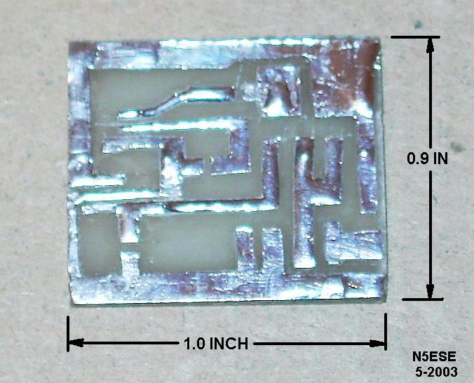
In keeping with the spirit of the AT-Sprint (which is 95% surface-mount), we decided to build this circuit using surface-mount techniques throughout, even though some of the parts are through-hole parts. This isn't hard to do. After a little planning with a pencil and a greasy yellow sheet of paper, we grabbed our hobby knife and a small 1 x 0.9-inch piece of raw scrap PCB, and proceeded to make our printed circuit. I am fond of the technique I use, dubbed by the late Doug DeMaw W1FB as "cut and peel". It's easy - you decide what doesn't belong, you cut around those edges carefully, and you lift up the copper, which "peels" off the board (with practice).. What I end up with (after tinning with a soldering iron) looks like this:
The real beauty of surface mount, is that there are no drills! Ever try to drill a small board like this? It ain't fun, and I always seem to mess up a hole or two or wipe out a trace.
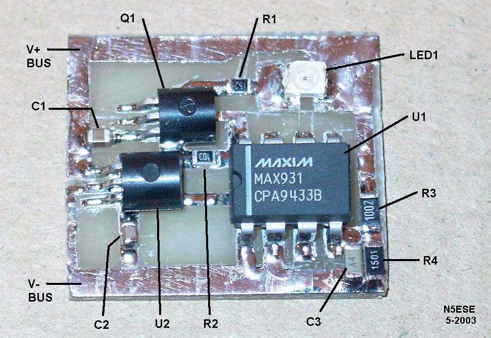
When you go to assembly, you simply align the part carefully on its pads, and apply a teensy-eensy bit of solder (beginners ALWAYS use too much solder, and I confess some of the joints you'll see here are globbed on a bit too much). Here's a view of the completed board, annotated with reference designators from the schematic. R4 consists of two resistors in parallel, stacked one on top of the other.
Is it really that small? Check out the picture below:
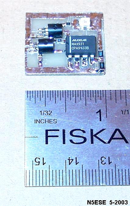
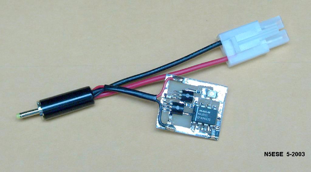
We ended up installing this little gizmo onto an adapter cable that goes from the battery pack to the connector that the AT-Sprint uses. You can see a picture of it at the top. Before we went to the field, we took some clear plastic and wrapped the board in it, so that it wouldn't inadvertantly short to something, yet we can still easily view the LED.
The "Put Up"
Fact is, this little baby works great! Next field trip, after about 4-1/2 hours, we noticed the LED blinking in sync with my keying. In about 10 minutes, I had wrapped up my QSO, and in about 5 more minutes, the light turned on continuously, and five minutes later, the unit died. Perfect!
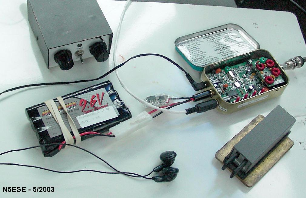
Here's a picture of the whole setup deployed in the front seat of my car. You'll have to look closely, but I think you can find the battery warning gizmo.
73,
monty N5ESE