(click on any picture to see larger version)
This web page describes my experience with the original AT-Sprint, which I built in June of 2003. There have been at least four versions since then, and none of the notes and mods on this page apply to those subsequent versions. Unless you're just now building that original model, or doing a historical review, this page will be of no interest. For information on subsequent versions, the best resource is probably the QRP-L maillist at http://mailman.qth.net/mailman/listinfo/qrp-l or look up Steve Weber KD1JV.
Steve alluded to - and I may have been the unwitting witness to - a potential and destructive problem with the final amp and amplifier keying circuit. The symptom I noted was that the receiver was weak, and the transmitter put out milliwatts instead of watts. Everything else seemed normal. Turns out that one or all of the final transistors (Q3/Q4/Q5 2N7000) were partially turned on all the time (as a result of damage caused by ?), and the TX Key switch Q7 (BCP69) was shorted B-C and open B-E. Rather than expound on it, I'll link to my e-mail to Steve regarding my theory, and his response. Please read in order, so it makes sense:
Four mods, both related to potentially destructive cold-boot problems; I recommend the first, strongly recommend the second, and third, and you can use your best judgment about the fourth:
Mod 1: Q7 Base Current Limit Resistor
In addition to the pullup resistor noted above, I added a resistor in the base circuit to limit the peak current in Q7during power-up. You see, during a cold power-up, when C45 is discharged, the only thing limiting current through the E-B junction of Q7 (until C45 charges) is copper loss and the junction itself. This could potentially take out Q7, which is rated 2A max peak current. To prevent this condition, I added a 10-ohm resistor in the base circuit of Q7. This could be as low as 6.8 ohms (but I didn't have one that low). On the PCB, I found a trace going from the Q7 base to R21, and removed it. Then I mounted a 10-ohm 0807-pkg SMT resistor where the trace used to be, soldering one side to R21, and the other side to Q7-Base. The resistor has virtually no effect on the normal operation of the Q7 circuit, but it will keep Q7 from blowing on power-up (mine blew, but I'm not sure why). To see how I handled adding the current limiting resistor, click -here-
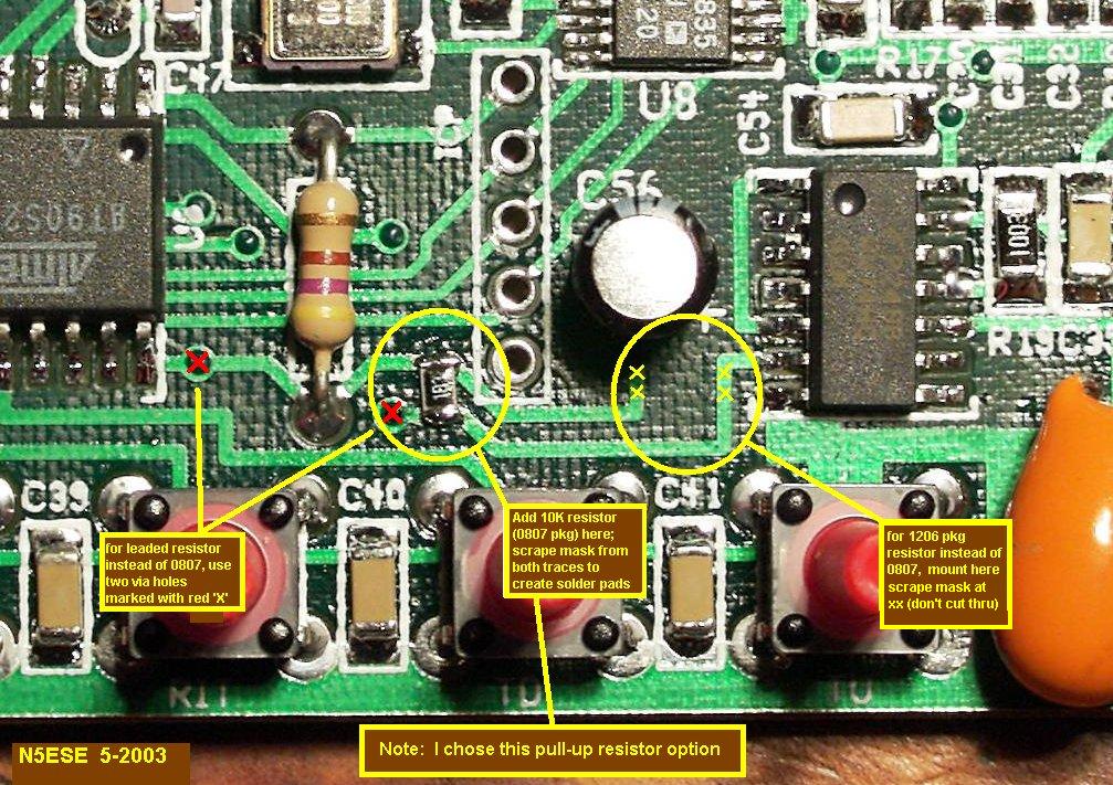
Mod 2: uC I/O Line Pullup Resistor
Adding the pullup resistor that Steve and I discussed pretty much cured any possibility of damage to the finals caused by undefined operation during power-up/boot. I plugged and unplugged power a hundred times to make sure all was swell, and it was solid as a rock. Before, I managed to kill two sets of finals with 4 or 5 tries. This mod also makes it unecessary to disconnect the antenna when powering up the unit. Electrically, the pull-up resistor is a 10K resistor from U6-2 to the +3.5V Digital Supply. It assures that the output of U5 (which gates the drive to the finals Q3, Q4, Q5) remains inactive during the boot process, which can take up to 1 or 2 seconds (plenty to blow a transistor in an RF circuit). To see how I handled adding the pull-up resistor, click -here-
Mod 3: DDS Power Mod
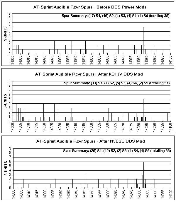
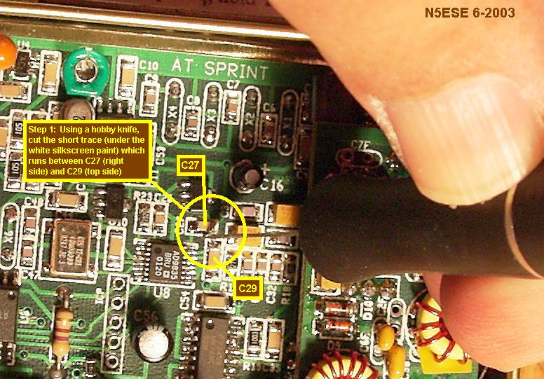
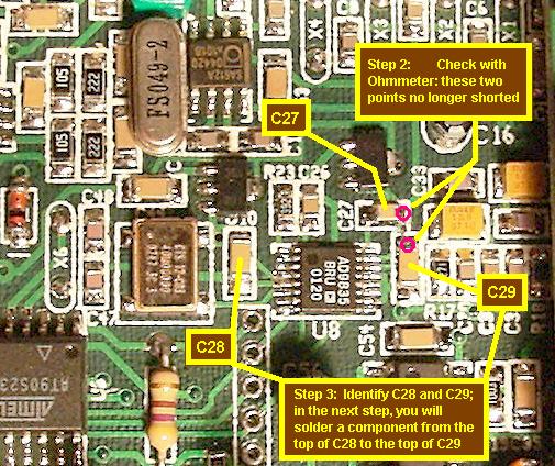
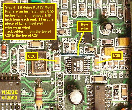
I found out about this one when I received an e-mail from the designer, Steve, KD1JV, describing the necessity for doing this mod. For that background, read his e-mail -here-. Since this problem could potentially destroy the DDS chip (although mine easily had 100 power cycles and 20 operating hours on it), it's a real good idea to do this mod, for three reasons: 1. The chip is sometimes hard to get on short notice; 2. The chip is expensive ($10+); 3. The chip is a bear to pull and replace successfully. Ideally, the chip would run from two well-isolated supplies, one for the internal digital circuitry, and one for the internal analog circuitry. This helps maintain maximum isolation, and prevents increased spurious outputs caused by a small portion of the digital trash making its way into the analog output. However, because of this mod, the DDS chip must now run on one power supply (the digital power supply). I was a little worried about this, as my unit already had a number of audible spurs in the receiver. Let me explain, for those DDS fans who get defensive about the "spurs" issue. In the state-of-the art monolithic DDS (which the 9835 certainly is), there will still be many, many digital spurs. The manufacturer says to expect the strongest of these spurs to be roughly 72 dB down from full output, assuming you follow their layout and filtering suggestions (which Steve did, as far as I can tell). 72 dB down sounds like a lot - we can ignore any spurs below that, right? But when you realize that the typical S3 or S5 signal is another 50 or 60 dB down below that, then you begin to understand why one can often hear audible tones as one tunes around a receiver with a DDS VFO. In my AT-Sprint, 90% of these are in the S1-S2 range, but there are a few as high as S4 and S6. The weaker spurs are likely masked by atmospheric noise when you hook up the antenna, but those S4 and S5 spurs sound like somebody tuning up. Even so, they're usually not problematic... it's not impossible to copy a weak signal near a steady tone slightly off frequency, for example. I knew about these spurs, but hadn't quantitized them. But when this mod came along, I was a little worried that running the DDS off a singe digital supply might increase the spurious content in the receiver. So I decided to do a "before and after". With a dummy load connected, and using the 20 meter module, I tuned in 100 Hz steps through the first 100 KHz (whew!), and tabulated the audible spurs by ear (very unscientific). Wow! That was an eye-opener. There were (17) S1 spurs, (15) S2, (4) S3, (1) S4, (1) S6 (totalling 38). That was before the mod, as suggested by KD1JV. After the mod, I did the same exercise all over again, and discovered a 40% increase in the number of spurs, and an overall increase in their strength: (33) S1 spurs, (7) S2, (5) S3, (4) S4, (2) S5 (totalling 51). This did not make me too happy, especially the increase in number of stronger spurs. So I decided on an alternate mod, which I'll offer here, in addition to that suggested by KD1JV. In my mod, instead of a wire to connect the analog V+ side to the digital 3.5V supply, we'll use an 820 uH molded choke, offering a high-impedance to some of that digital trash. Also, we'll bolster the decoupling capacitors on both sides somewhat, by piggybacking some high quality X7R 0.1 uF surface-mount chip capacitors in parallel with the existing decoupling capacitors, C28 and C29. The result was gratifying. Now, our survey of spurs resulted in a slightly better count than the original configuration (i.e., before mods), and with somewhat reduced levels. After the N5ESE mod, the spurs count was: (20) S1, (12) S2, (2) S3, (1) S4, (1) S6 (total 36). If you'd like to see a chart with the spur distribution and strength plotted, click -here-. If you'd like to play with the EXCEL data, click -here-. OK, so what follows here are both mods, described in three images, with the last image of your choosing (i.e., KD1JV's mod, or mine, N5ESE's mod):
-Step1- ... -Step 2 & 3- ... -Step 4 KD1JV- ... -Step 4 {N5ESE)-
Incidentally, a clarification about these spurs: very few of them are "tunable". In other words, they appear as tones at a particular tuning position (100 Hz steps, in this case), representing the unique digital signature of that tuning number on the numeric oscillator. For example, If an S6 spur appears at 14087.3, it probably will not appear at 14087.2 or 14087.4, even though a true signal at that audible frequency could be tuned as long as it was within the IF passband. Nonetheless, there are a few tunable spurs, and I suspect these are true mixer products, rather than DDS spurs, though the DDS spurs may be a contributor.
By the way, the receiver spurs problem can be exacerbated by layout issues not related to the PCB layout and filtering. I wonder if my putting it in an Altoids tin doesn't also thwart the decoupling and isolation that might have made the spurs less numerous or less noticable. I mounted the board at 4 points using metallic screws; it may have been better to mount them using non-metalic screws, and let there be only one single-point ground - the point where the RF output connector touches the Altoids tin. I'll report on that as another subject matter, at a later time (too many fires, you know). In the meantime, if you've managed more insight into this problem than I have, drop me some email.
Mod 4: Band Module Diode Limiter Mod
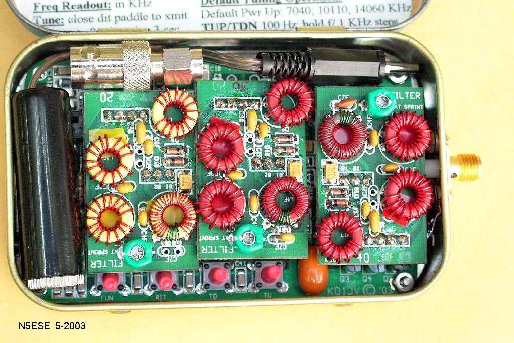
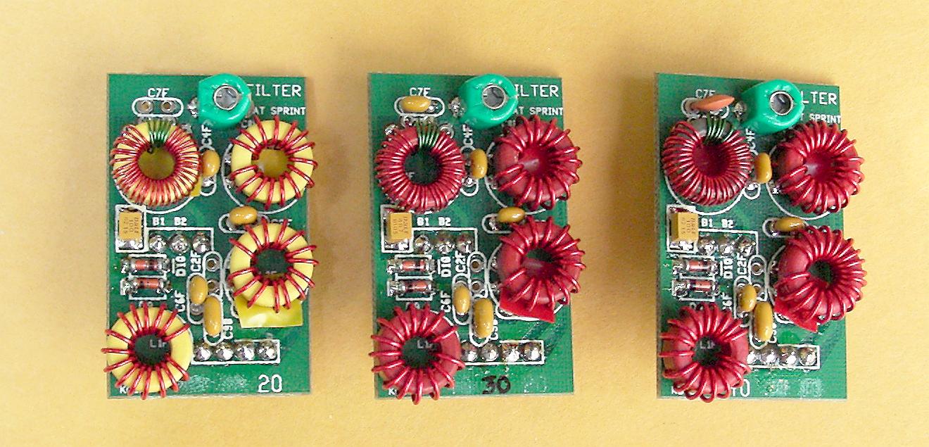
The band plug-in modules (there are three, one for each band) contain a diode limiter as part of the lumped-LC-quarter-wave T/R circuit. The limiter is made up of back-to-back 1N4148 diodes. Some folks reported distortion in the presence of very strong signals, and that's not too hard to believe. I wanted to use the AT-Sprint on the upcoming Field Day, and I knew this would be a "worst case" environment for the AT-Sprint. Therefore, I increased the limiting as suggested by one of our European friends (sorry, I forget who) to 3 diodes in series (in place of each diode), for the 40 and 20M band modules. For 30 Meters, I used just 2 diodes in series for each diode. I'll let the pictures show how it was done, but I used surface-mount 1N4148's that I got from Frys Electronics locally. To see the 20 and 30 Meter details, look for D9 and D10, just north of the lower-left-hand toroid in -this picture-
By the way, the results of the diode mod were good. On FD 2003, we experienced only two incidences of receiver overload during 16 hours or so of operating, both on 20 Meters. The mod results in a slightly increased "tick" sound with keying, in the sidetone only, and very mild.
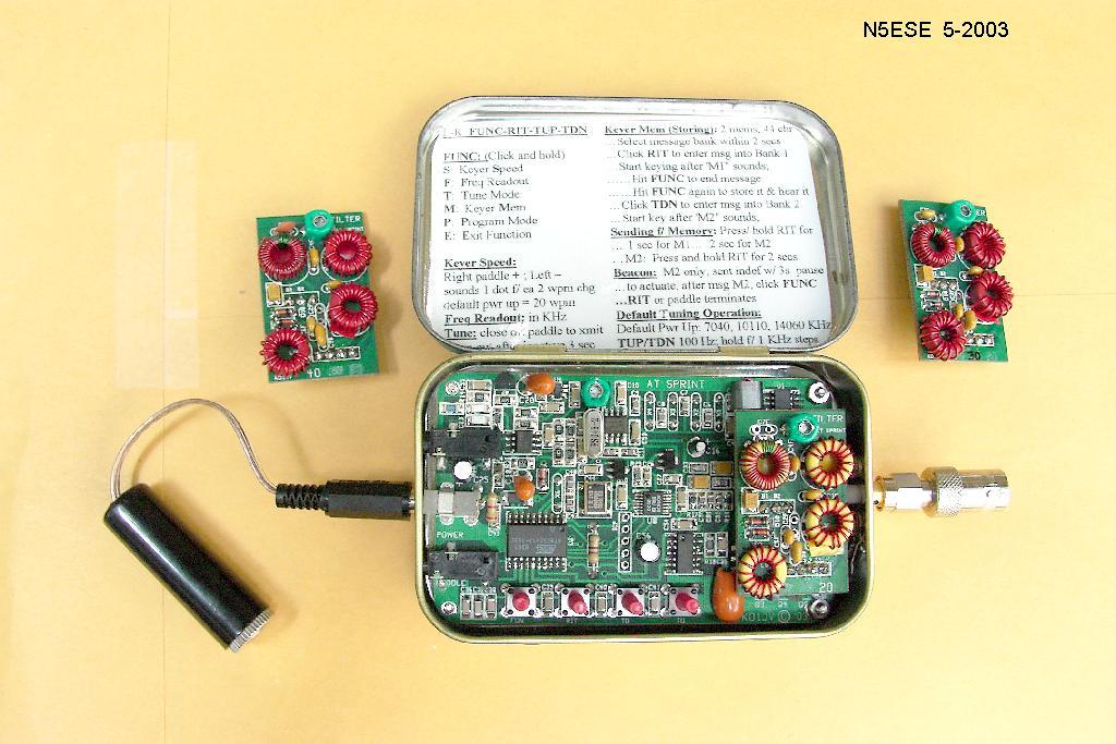
Here are a few more pictures, followed by links to yet more...
(click on any picture to see larger version)
(click on any picture to see larger version)
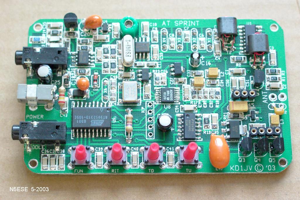
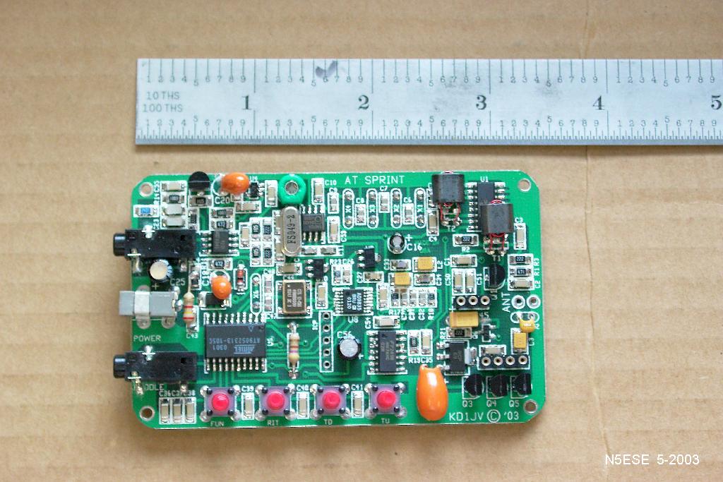
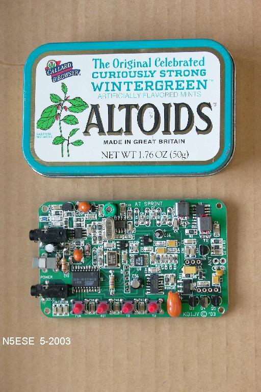
The AT Sprint is an Altoids-sized 3-band CW Transceiver Kit with a microprocessor-controlled DDS VFO, superhet receiver, and Class E finals for 4 watts output. Amazing, eh? For more info, visit the designer's web page: Steve Weber KD1JV
Performance Observations:
Power Usage (at 12.55 VDC):

--------------------------

RX (no signal).........  50 mA

RX (S9 signal).........  54 mA

TX (final disabled)....  72 mA

TX (final into 50-ohm).  630-690 mA

                        (depending on band)


Receiver and AGC Performance:

----------------------------


Freq    MDS      AGC-LO    AGC-HI    DESENSE

----    ---      ------    ------    -------

7040    0.1 uV   8 uV      800 uV    >1000 uV

10110   0.1 uV   3 uV      300 uV    > 400 uV

14060   0.1 uV   9 uV      900 uV    >1000 uV


Note:  AGC-LO is when signal rises to 90% of its maximun audio volume at headset

       AGC-HI is when signal drops to 90% of its maximun audio volume at headset

       DESENSE is when stronger signal decreases & becomes distorted in headsets

Note 2:  These results were observed BEFORE the diode mod, described above,

       which may or may not affect the "desense" threshold.


Receiver Selectivity (Antenna Port to Headphones):

-------------------------------------------------

-20 dB (LOW)    552 Hz

 -6 dB (LOW)    569 Hz

  0 dB          703 Hz

 -6 dB (HI)     864 Hz

-20 db (HI)    1179 Hz


 -6 dB Bandwidth = 295 Hz

-20 dB Bandwidth = 627 Hz


Transmitter Performance (V-BATT = 12.55 VDC):

--------------------------------------------


Freq    PWR-OUT    I-Total    Eff (Final)

----    -------    -------    -----------

7040    5.76 W     0.63 A        75 %

10110   5.44 W     0.69 A        70 %

14060   4.92 W     0.67 A        65 %


Note:  Final Efficiency calculated by removing

72 mA from I-Total (for supporting circuitry)
Test Day (in the Field)!
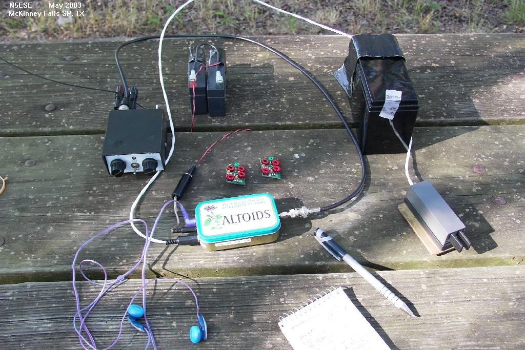
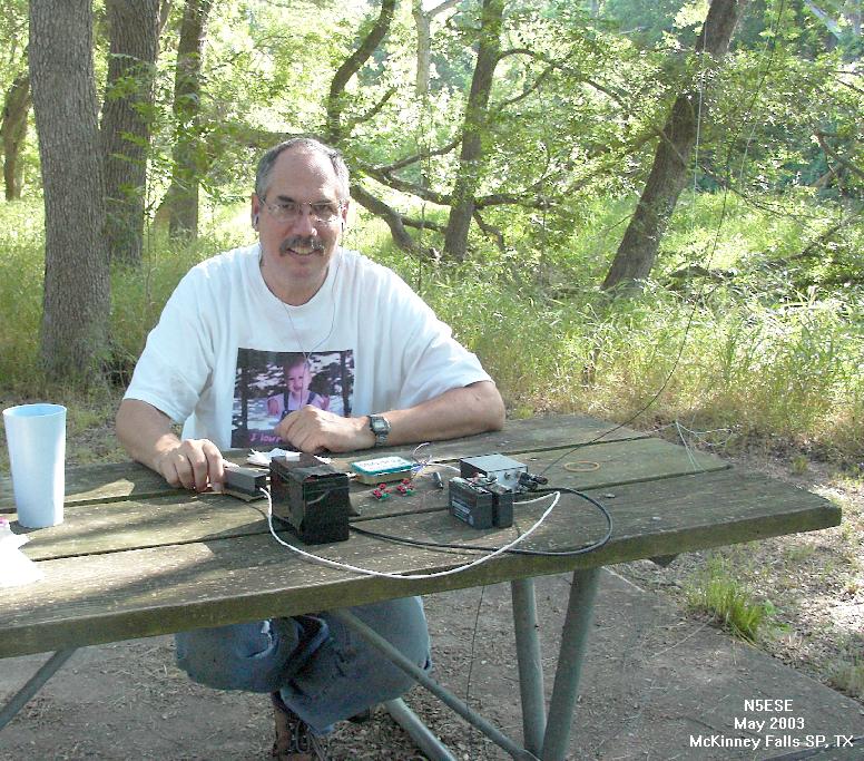
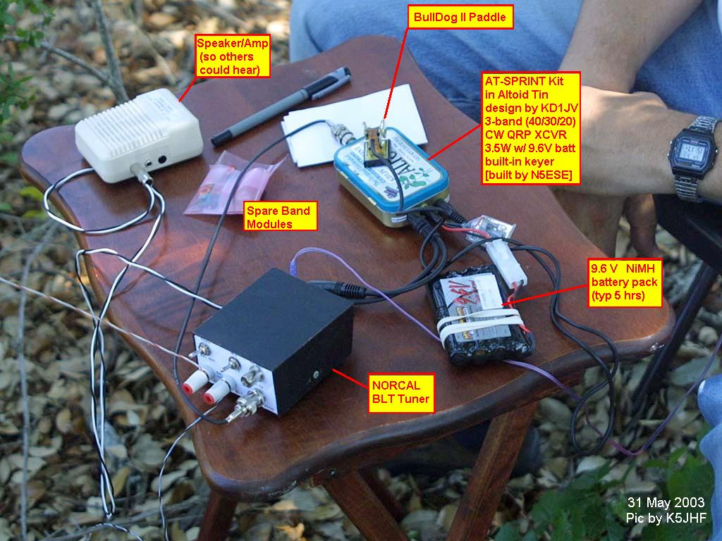
First outing to McKinney Falls State Park in south Austin, TX, we set up using a 12 V, 1.2 AH Gel Cell and a Palm Radio mini-paddle for keying. For an antenna, we used a 50 ft vertical wire, worked against (4) 32 ft radials and (2) 16 ft radials. A Norcal BLT tuned it nicely on 40 and 20, and needed help from a 1:4 balun on 30M. [In fact, I never got a really good match on 30 Meters, and no solid contacts either). After 3 hours of casual operating, the gel cell was down to 12.35 V at transmit. During that time, we had four QSOs, all lasting 15- 20 minutes each: XE2RN (Rich, in Baja, Mexico, 20M); WB9WZN (Bill, in Gary, Ind, 20M); KG8YT (Bruce, in Marquette, Mich, 20M); and N0EVH (John, in Kansas City, MO, 40M). Amazingly, all contacts were 2-way QRP! All gave good reports on keying, but I've not had time to give a critical ear to listen to the keying and tone myself - but I'll do that soon...
I'll post a more thorough description and review, and tell about other minor mods I made to the AT Sprint, when I get a little more air time (and spare time). In the meanwhile, I offer these pictures.
More Preliminary Pictures & Stuff (unsorted):
Resolution 1024 x 768:
Main Board, Top View A
Main Board, Top View B
Main Board, Top View with scale
Main Board next to Altoids Tin
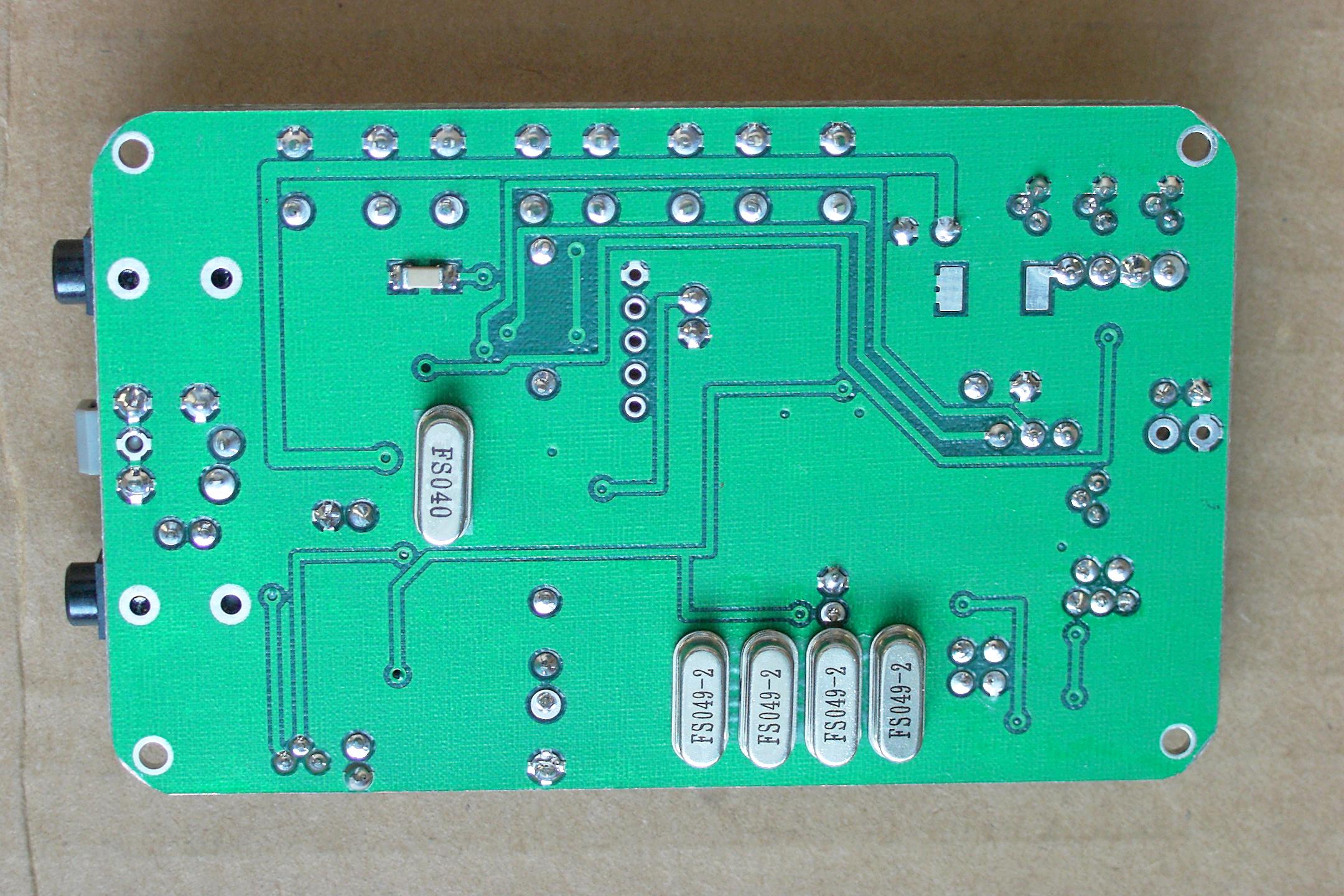
Main Board, Bottom View
Band Modules (20, 30, 40, L-R)
Portable Ops with the AT Sprint - Equipment on Picnic Table
N5ESE during Portable Ops with the AT Sprint (one happy op ;-)
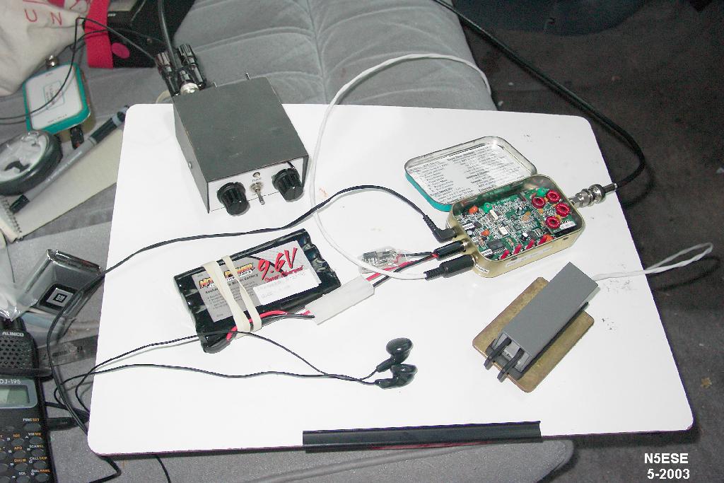
Portable Ops with the AT Sprint - Equipment in Car
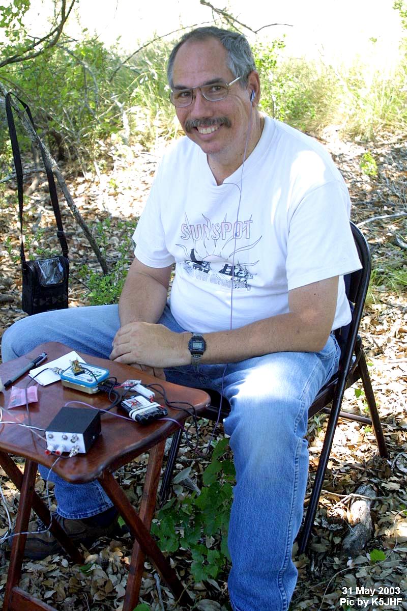
N5ESE during Portable Ops at K5TR's hill country ranch
Portable Ops at K5TR's with the AT Sprint - Equipment (annotated)
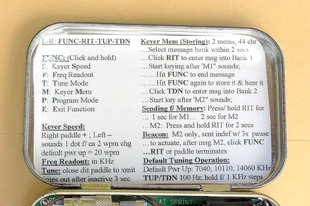
Quick Reference Stick-on Label (mounted on inside cover)
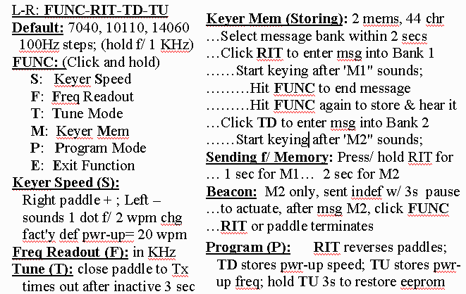
Updated Quick Reference Stick-on Label (image - resize to fit inside cover)
For an MS Word 97 Document File of the above Quick-Reference Label, click -here-
Resolution 2160 x 1440 (very large, 500KB+):
Main Board, Top View
Main Board, Bottom View
73,
monty N5ESE