N5ESE's 40 dB Tap Attenuator
(click on any picture to see larger version)
(click on any picture to see larger version)
In recent years, we've seen great advances in monolithic semiconductor detectors built for receive (RSSI Detectors) and transmit power detection. Some examples are: the Analog Devices AD8307 and AD 8362, and the Linear Technologies LTC5507. These devices have a string of high-bandwidth logarithmic amplifiers followed by a highly compensated detector with unprecedented overall measurement accuracy of up to +/- 0.5 dB (about 10% of the power) over a range covering audio to 500 MHz or even higher. And that, over a measurement range from picowatts to milliwatts. Try to do that with your 1N34 !
Being able to accurately measure RF circuitry down into the milliwatt range is amazingly useful for those of us who "homebrew" radio gear, or who operate QRPp (output power in the sub-watt range). But nearly all of us venture above the 10 milliwatt level, and it would be really, really nice to extend the measurement accuracies we see with these new chips, up into the watts and hundreds-of-watts range.
What I describe here is an accurate 40 dB (power factor of 10000) tap attenuator, usable with 50-ohm matched circuits, which will allow you to extend the measurement range of the newer RF power detector chips to around 100-350 watts (depending on the chip's upper measurement limit). Useful upper frequency limit is something near or over 220 MHz (but I've only verified it to 148 MHz).
What's a "Tap" Attenuator?
The tap attenuator differs from an inline attenuator in a couple of ways: Inline attenuators must absorb large amounts of power. A 40 dB inline attenuator with 200 watts applied to its input must be capable of dissipating 199.8 watts (!), while accurately delivering only 0.2 watts to the power meter's 50-ohm input sensor. This is actually quite hard to do, because of the difficulty in maintaining accurate resistances with the component heating that necessarily takes place. As a homebrew project, an inline attenuator with this capability can be a frustrating, time-consuming, and expensive task. By contrast, a 40 dB tap attenuator need only dissipate 2.3 watts, while delivering the same 0.2 watts to the input sensor. And it's quite do-able.
Let's look a a schematic for a 40 dB tap attenuator:
On the left, we see a typical test setup for a ham transmitter. It could as easily be any other source (an RF driver or predriver stage being homebrewed, for example). The transmitter feeds a 50-ohm dummy load (dry dummy, Cantenna, bank of resistors), which acts as the stable load for the transmitter. The dummy load is important, because it absorbs the power coming from the transmitter, without radiating. We could also use a radiating antenna as the load provided that it is matched and looks like 50-ohms resistive. That would be the case at the input side of a properly adjusted manual or automatic antenna tuner.
One method of measuring power on such a setup would be to use a diode detector (like our own RF Probe project), and compute the power using the formula E * E / R, where E is the RMS Voltage across the dummy load, and R is 50 ohms. This actually works quite well, as long as you have several volts, and you don't exceed the diode's voltage rating. But those two restrictions make it a difficult task to accurately measure powers much below 1 watt or much above 25 Watts. The modern RF Power chip, however, with the proper attenuator to isolate it, can easily measure from nanowatts or microwatts up to 100, 200, 300 or more watts.
But back to the schematic. As you can see, we've inserted a "TEE" connector into the line running from the transmitter to the dummy load. This forms an electrical junction where we'll attach our "Tap" attenuator. This is the point where we would measure voltage if we were using an RF probe. Instead, the tap attenuator forms a voltage divider consisting of R1 (ideally 4950 ohms) and the RF Power Meter Input's 50-ohm load. The voltage at the RF Power Meter's input is then 1/100 of the voltage at the dummy load. The tap alters the dummy load's nominal 50-ohms by a minute but negligible amount (49.5 ohms instead of 50 ohms), which can be ignored. Since we know the voltage (at the Power Meter) to be 1/100th of the voltage at the dummy load, we also know that the power at that sensor load will be 1/10000 (i.e., E * E / R) of the power at the main dummy load. That's -40 dB (i.e., 10 log 0.0001)
There's just a wee bit of a twist we must deal with, with this kind of attenuator. If there is some stray capacitance between the TEE junction and the Power Meter's input, it will tend to shunt higher frequencies around the tap resistor, R1. The effect is that more voltage will be delivered to the Power Meter Input as the frequency increases, making the meter read high at high frequencies. To compensate for that stray capacitance, we add a capacitor in shunt with the Power Meter input. That capacitor forms an RF volatge divider (with the stray capacitance), maintaining the same 1/100 voltage division that the resistors do. Unfortunately, we can't perfectly predict what the stray capacitance is, so we have to make that added capacitor a trimmer-type. During alignment, we'll tweak it so that it reads properly at high frequencies, thus flattening our curve so that we end up with a good broadband attenuator.
If you want to learn more about the operation and limits of the 40 dB tap attenuator, from a theoretical and practical point-of-view, I've written a white paper relating my experiences with SPICE simulations and component calculations, and you can see that -here-.
OK, So Let's Build One!
For some reason known only to my deviant Id, I like to build dummy loads and attenuators into copper pipes, and radios into Altoids tins. (it's a sickness...). That's the approach we'll take here. Except for the 3 plumbing pieces (3/4" pipe hardware: 2 end caps, and a repair coupling), which I bought from Home Depot for about $4, everything came from my junkbox. The number and combination of resistors was selected based on what was available. As long as your resistor combination is reasonably close to 4950 ohms, and will safely dissipate 1/100th of the full power to be applied, and you use resistors with good RF properties (metal film, thick film, carbon film, carbon composition, metal-oxide resistors), you should be OK.
I think pictures say a thousand words, so we'll show the assembly step-by-step, and hope it makes sense. Click on any picture, you'll get a larger image with text annotations that may make things clearer.
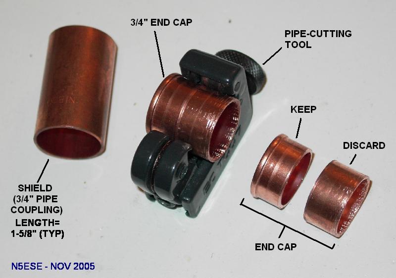
To make room for the internal assemblies, we need to cut down the end caps, using a pipe cutter. When done, the part which slips into the pipe is about 1/4" long (see above).
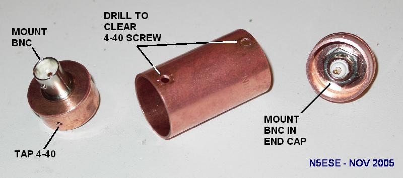
Then we insert the end caps in both sides of the coupler (it should be a slip fit), and carefully mark, punch, and drill a small pilot hole (one on each end). Then, remove the end caps, debur, and drill and tap the holes for 4-40 screws. On the shield (formerly, pipe coupler), drill two holes (one on each end) to clear 4-40 screws.
Next, very carefully find the center of the end cap, and drill a 3/8" hole to mount the BNC jack. In one end cap, mount a BNC jack with no ground lug, relying on the mounting hardware for connection to ground. This will be the transmitter end. On the other end cap, mount a BNC Jack with a solder lug and hardware. The solder lug will be needed later. Note: good ground/shield conductivity is important for proper performance of the tap... make sure you have good electrical and mechanical connections from the BNC to ground and lug.
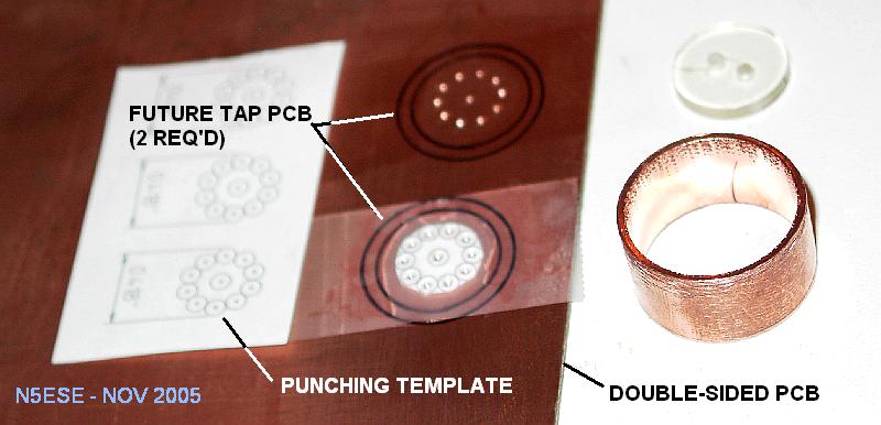
We're going to fabricate two small pc boards for mounting the resistors, and we'll use brute-force methods. Take any available double-sided copper clad board, and mark two circles, using the inside diameter of the discarded piece of the end cap. Then take a button (or other suitable object), and mark an inner circle. The inner circle should mark about 1/16" insulating space within the outer circle. I made a full scale template for marking hole centers, based on ten 1/4-watt resistors. I then aligned it carefully within the marked inner circles, and center punched the resistor pads and center hole.
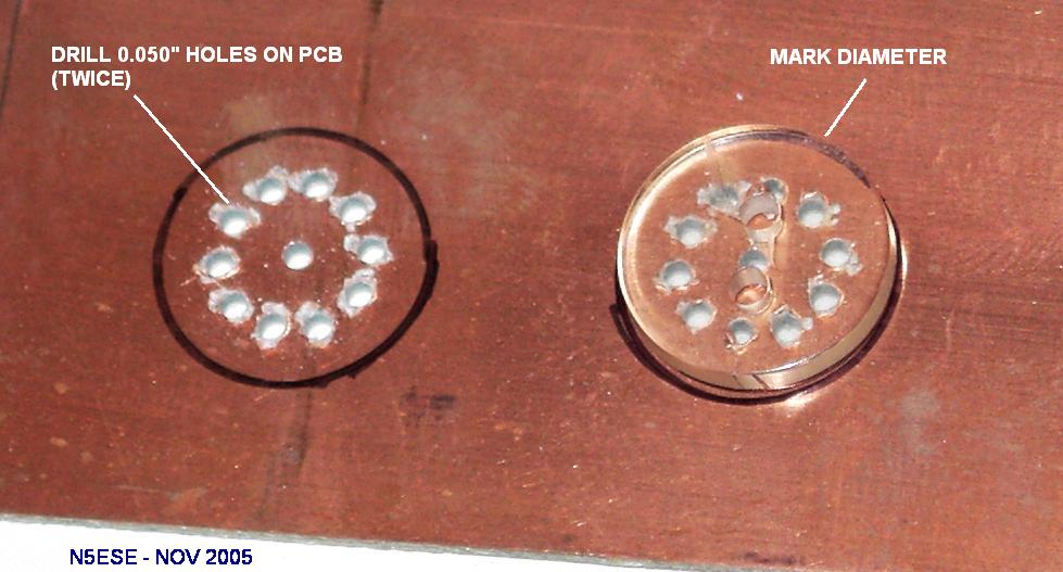
Next step is to drill the center punched holes. I used a 0.050" drill, and it might have been a little large. 0.035" would have been a better fit for the resistor leads. The center hole on one PCB should be drilled to about 3/32" inch diameter, and on the other to about 1/4 inch diameter. Also, flip the board over to the unmarked side (after you've drilled it), and using the button you used earlier to mark the inside hole, mark a circle over both drilled patterns.
Now (back to the first side), use whatever suitable cutting tool you have to cut the two PCB's on the OUTER circles. I used a nibbling tool, and then filed the rough edges smoothly round by hand (see Warning below!). The finished board was about 3/4" in diameter. Now, remember the inner circle? and the one marked on the other side? Using a hobby knife (see Warning below!), and score a circle on both sides of each PCB where you marked the circle. Then peel the copper off, forming a copper-less ring about 1/16" wide around the outer edge on both sides.
| WARNINGS! |
| 1. Fiberglas dust (from filing and cuttng operations on printed circuit board materials) are hazardous to your health if breathed in. Use a dust mask, or otherwise make sure the particles do not become airborne (difficult to do). Also, protect others in the area. |
| 2. Hobby knife blades are prone to breaking, especially at their tips, and can become projectiles with unpredictable paths. Don't risk your eyes! WEAR Eye Protection! Also, protect others in the area. |
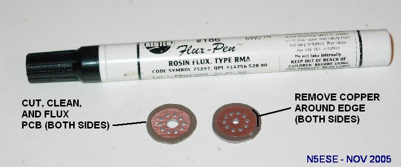
At this point, the drilled holes are pretty raw, and the PCB may be somewhat tarnished. To remove drill burrs, I take a slightly larger drill bit, and using just two fingers and very light pressure, twist the bit to remove burrs. Then, remove and oxidation on the PCBs (both sides). My favorite way to do this is with a green 3M scrubbing pad. When you're done, the PCB's should be bright and shiny. Lightly coat both sides of the board with electrical grade flux. I like the Kester 186 Flux pen (shown above). Costs about $4 but lasts for years and years.
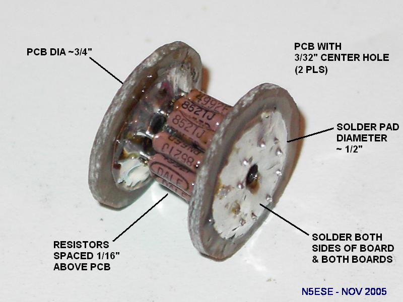
Now comes the tricky part: installing the resistors. Install all ten resistors into one board first, soldering on both sides, and keeping the resistor body about 1/16 inch from the board. Then, stagger-cut the free leads, and install the other board, again soldering each resistor on both sides, and leaving the 1/16" spacing. When finished, both boards should be reasonably parallel, and each resistor lead should have two solder joints. See above
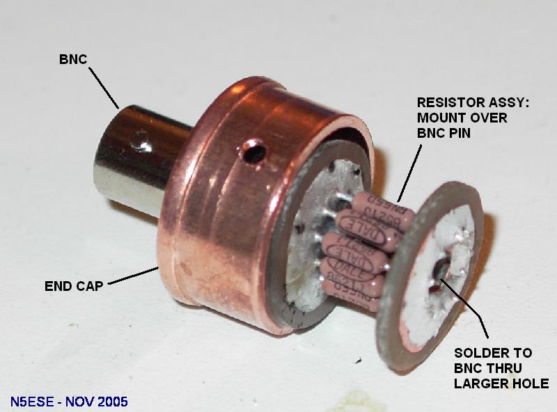
Now, slip the smaller hole of the resistor assembly over the center-pin of the BNC on the transmitter end (the end with no ground lug). Solder the PCB to the center post (a little flux may help). The larger hole will provide access to the solder post for your soldering iron tip. Make a strong solder joint here.
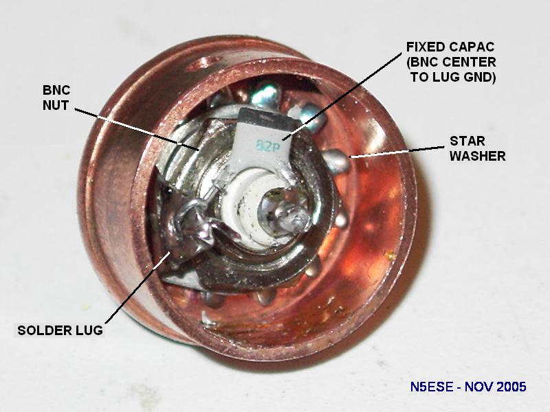
Grab the end cap that has the BNC jack with the solder lug. Install the 82 pF capacitor between the solder lug ground and the BNC center pin, tucking the capacitor down inside the end cap. Solder just one side lightly, so as to keep the part in place, because we have more connections to these points later.
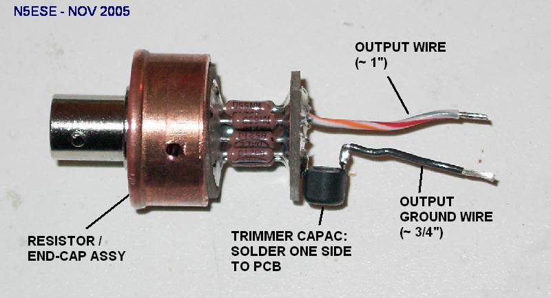
Find the end cap with the resistor assmbly, and install the trimmer cap by soldering one leg to the resistor PCB. Position the trimcap so that it's trimming screw will point radially outward, and will still fit within the shield (pipe coupling) when it is mounted later. To the other electrical terminal of the trimcap (sometimes it is opposite, sometimes at 90 degrees), attach a 1-inch piece of stranded hook-up wire. Teflon insulation wire with a small diameter and high strand count is preferred for flexibility, but use what you can get. Then, attach a similar piece of wire to the resistor PCB itself.
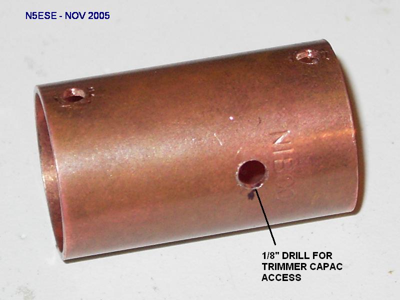
Without hooking up the wire, fit the resistor assembly into the shield (pipe coupling), and screw it in place. Leave the other end cap unconnected, and carefully measure and mark (on the shield) where to drill the access hole for the trimmer. Then, remove the shield, center punch the mark, and drill an appropriate hole (roughly 1/8").
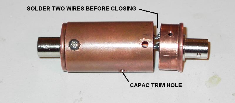
Reassemble the shield to the resistor assembly, screwing it together. Check the trimmer access hole alignment, Solder the two wires as follows: wire from trimcap goes to ground lug; wire from resistor PCB goes to center pin. Make sure both the wires and the 82 pF capacitor (you mounted earlier) have good, clean solder joints. At this point, your assembly should look as above, just before closing it up.
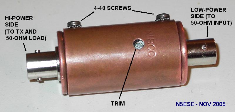
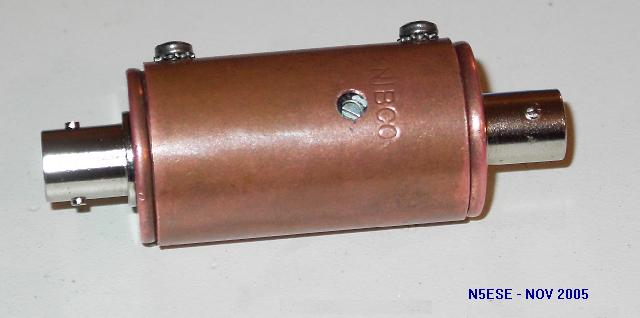
Close up the assembly, screwing the end caps securely to the shield. Admire your work, which should look something like the above image.
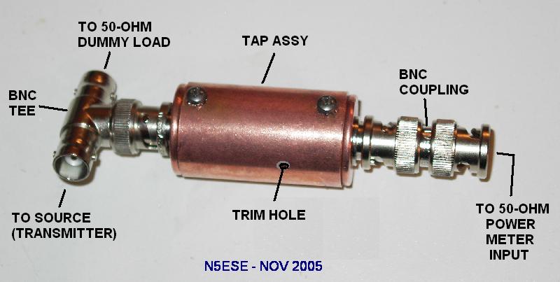
To use the tap, you'll need a BNC-TEE adapter, and a BNC female coupling adapter. It's important for proper operation that the minimum length be used from the tap assembly to the measuring instrument, and from the tap assembly to the transmitter feedline, and the adapters help accomplish that. Both adapters can often be obtained from your local Radio Shack, or your favorite online electronic distributor.
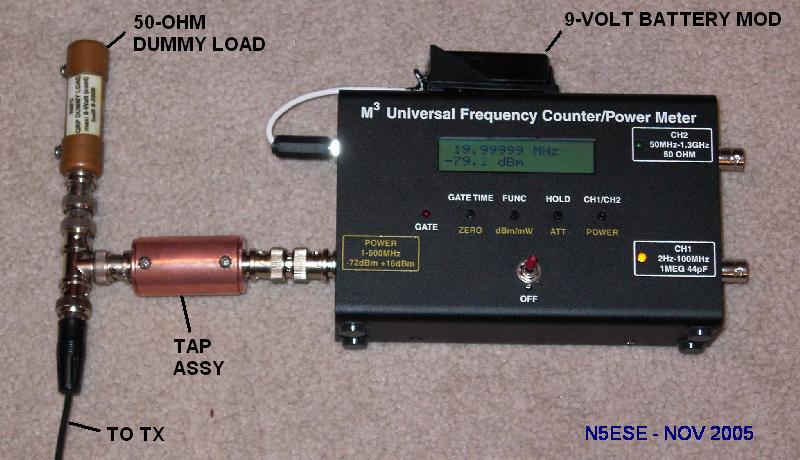
Above, is a picture of the connections to the Power Meter and the dummy load. The dummy load shown is one of my QRP gizmo projects, which you can see -here-. You could as easily use your 250 watt dry or wet dummy load. I prefer to have the TEE connected right at the dummy load, where the load impedance is (presumably) 50-ohms. But if that's not possible, anywhere along a matched 50-ohm feedline should work OK.
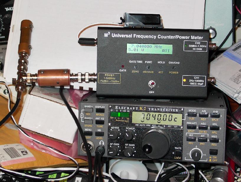
Finally, let's see the tap attenuator in operation. Above, you can see it measuring the output power on my Elecraft K2, and the power meter is indicating 5.01 watts on 40 Meters. Don't look at the clutter all around it... yes... I know... I'm a slob...
73,
Monty N5ESE
dit dididit dit