N5ESE's QRP Dummy Load
(click on any picture to see larger version)
(click on any picture to see larger version)
| NOTE: 'N5FC' is my former call. This project was constructed while that call was valid, and you may observe references to it. |
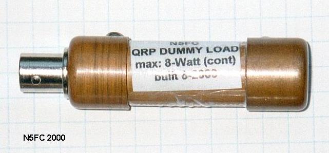
This is another variation on the "parallel resistor" dummy load. [Go -here- for a discussion on dummy load theory]. This is one I built during my infatuation with copper pipe. It's perfect for QRP HF operation of 5-watts or less average power, and should be adequate for continuous operation at that level. It's light and compact, about 2-1/2" in length overall.
The 1/2" copper pipe provides a convenient, compact form factor, is an excellent shield, and helps to dissipate heat to the outside world. Copper end-caps, available at most any hardware or plumbing supplier, provide a means of mounting the UG-1094 BNC jack and closing the unit.
This version uses 8 each 100-ohm 1-watt 5% metal-oxide resistors. Available from Radio Shack for a mere 25-cents each (RS 271-152), you'll invest all of $2 for the parts. The resistors are good through the HF range, but don't do particularly well at VHF. Here's a schematic:
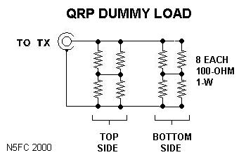
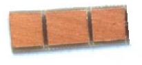
We'll fabricate a printed-circuyit board from scrap double-sided copper board, cut to 1/2 x 1-1/2-inches, and grooved to form 3 pads on each side. On the top side, we'll mount 4 of the 8 resistors, and on the bottom side we mount the remainder. Simply tack-solder the resistors to the board. At the pads on the ends, we drill a small hole through the board, and solder a wire in place top-to-bottom. On the top side, we end up with a 100-ohm, 4-watt equivalent resistor (a pair of parallel 100 ohm resistors makes 50 ohms, and two pairs in series make 100-ohms). When we join the top and bottom in parallel, our equivalent resistance is 50-ohms (two 100-ohm quads in parallel).
Here's a sketch of the pc-board layout:
Mount the UG-1094 BNC Jack in one of the copper end-caps. then, connect the pc board assembly directly to the center post of the BNC connector, soldering same. Connect the far end of the board to the BNC ground post, via a short piece of bare wire. Wrap the entire pc board assembly liberally with plumber's teflon tape (available for a buck in the plumbing section of any hardware store). Then run the bare wire outside the teflon tape. DO NOT use other types of tape (they will melt!). Next, we slide a short piece of 1/2-inch copper tubing over the assembly, slipping it into the BNC/end-cap. At this point, an ohmmeter should verify 50-ohms. Finally, mount the other end-cap to close and shield the unit. Drill and tap a screw into both end caps to connect the shield both electrically and mechanically.
When supplied RF power for an extended time, this dummy load can get quite warm, even with just 5 watts. Be aware, and plan for it. (Read the "WARNING!" above). My version has an SWR of 1:1 throughout the HF range (DC to 30 MHz). Another variation of this, that includes an rf detector for measuring power, can be viewed -here-.
73,
monty N5ESE