N5ESE's DCTL Portable Antenna
(Prototype)
A Low -Power Indoor Portable HF Antenna
by Monty Northrup, N5ESE
NOTE: 'N5FC' is my former call.
This project was constructed while that call was valid, and you may observe references to it. |
|
Antenna Disclaimer
|
Right from the top of this page, I'm going to say that I'm an antenna experimenter, not an antenna expert. Purely seat-of-the-pants. In fact, you might even say I'm an antenna cynic. I know how to use antenna analysis tools, and I often do, but I take them with a serious grain of salt. I've found, in my 35 years of experimenting, that some antennas work much better than predicted, and some work much worse (and that they're more likely to work worse than better HI HI ). Still, I find experimenting to be one of those true joys of amateur radio, and I encourage all of you to just "try it out" for yourself, and for Pete's sake, don't take my word for it (nor my explanations).
I find that most technical people do this (and I am no exception): upon observing a phenomenon, we make up an explanation for why we got our observed results. We base this explanation on the current subset of knowledge that we've gained from education and experimentation and folklore, and we're not likely to look for another explanation until we have another experience which forces us to expand or revise our previous explanation. Please realize this is the case with me, also, and then enjoy the web page.
If you really want to know how it works - without my ignorant rantings getting in the way of a thorough understanding - click -here-
|
(Pictures and Diagrams follow the narratives)
On this page, we'll describe our prototype of the DCTL (Distributed Capacitance Twisted Loop) Antenna. I did not invent this antenna. In fact, I know very little about how it works. I recently ran across a description of it on Marty Watt's (N5NW) web page. He credits Jim McLelland, WA6QBU for developing the design. Marty's page presents theory and construction details for each band.
Marty's N5NW call has been reassigned, and his new call is K0IN (clever) but his web page has disappeared.
I'm going out on a copyright limb here, until I hear from him, but I'll re-post his article.
Unfortunately, I have archived only a text copy of his page, sans two of the images, but you may find it useful:
N5NW's original DCTL web page (partial copy)
Here is a link to the original WA6QBU article:
WA6QBU Article July CQ 1994
While I don't yet have a lot of experience with this antenna, I like it a lot. This antenna is a good compromise between size and practicality and efficiency and economics, especially for portable and/or indoor use. I travel a lot, and I'm always looking for a very portable and inexpensive antenna. This one definitely fits the bill, costing less than $10 to build, and fitting inside a large zip-lock sandwich bag, which I can throw in my briefcase. In addition, it's a resonant design, which can be a big plus as far as radiation efficiency goes. Keep in mind, though, that this is a single-band antenna.
My own view on how this works is that this is a simple tank circuit, built out of distributed L and C (the shorted twinlead stub, and main twinlead capacitance loop, respectively). There is a "magic" length of twinlead L and C that provide an optimum resonant tank, and this tank occupies sufficient physical space to radiate freely into air. This also explains why the antenna works only on one band.
What We're Doing Here
As an expansion and clarification of Marty's DCTL web page, I offer the following images of my version, in addition to my experiences of it.
I've built two versions of this antenna, both cut for 40 Meters CW. One version used cheap 300-ohm twinlead, and the other used premium 300-ohm ladder line (to reduce IR losses). I discovered (by doing otherwise), that you can pretty much use the formulas provided by Marty to cut the various components for the antenna. Cut carefully, because I find the antenna is not forgiving of gross errors. By the same token, if cut accurately, it does not require any tweaking of the main loop or shorted stub. The first version I built (shown in the pictures) used el-cheapo Radio Shack twinlead (RS 15-004). I cut only enough extra length to accommodate my twist-and-solder joints. I thought that by using the formulas, I would not need the short capacitive stub, but my MFJ Antenna Analyzer showed resonance to be about 150- 200 KHz high. So I spliced in the short stub, starting with 8 inches, and cutting off 1/4-inch pieces until I got resonance at the desired frequency. At this point, the analyzer (which is designed for 50 ohms), shows an SWR of about 2.5:1. When I finished trimming the capacitive stub, the stub was about 3 inches long.
Now that it was resonant, all we needed was an antenna tuner to match the 50-ohm transmitter to the radiation resistance of the antenna. I have used both my MFJ-971 and Emtech ZM-2 antenna tuners to successfully obtain a 1:1 match. NOTE: This is a balanced antenna, and needs a tuner/transmatch with balanced outputs.
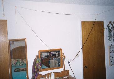
For testing, I hung the antenna using nylon cord, and cup hooks in the first floor bedroom ceiling, about 10 feet apart. The main loop was formed into an equilateral triangle shape, with the apex (and feedpoint) pointing downward. The shorted stub hung downward like a tail, almost touching the floor (see picture)
Results, and My Impressions
The day I built it, the 40 Meter band was in terrible shape, almost dead. While looking for a contact, however, I briefly heard a ZL (New Zealand) station calling CQ. His 599 (!) signal was there and gone in 15 seconds, but that convinced me of the antenna's receiving abilities. Later, running QRP 5 watts, I called a G3 (Britain), who was himself about S5, and who heard my signal, but could not manage to get the callsign, and gave up after a couple of rounds. But Hey! At least I knew the antenna was working, although not well enough for DX at QRP, and not well enough to overcome terrible band conditions.
Since then, I've tried several times to use the 40 Meter DCTL in a hotel room, while travelling on business. I've never been able to snag a QSO, though I have uncanny luck for timing my business trips with bad band conditions (why is that?).
Since I live in a duplex with a very small yard, I built a weatherproof version of the DCTL for 80, in hopes of circumventing some local hash noise, and maybe doing a little QRP PSK-31. While the antenna seemed to have plenty of receiving gain on 80, and loaded up very well on transmit, I only made two QSOs, with weak reports. One was about 300 miles away, and one about 600 miles. Both of the other signals were s9+, and I ended up QROing to 50 watts to get an s7 signal. Other attempts were twarted by the local hash noise, which became so bad that I gave up on 80 altogether, and gave the DCTL away to someone with a more reasonable chance of success.
As a receiving antenna, signal strength was about 1 to 1-1/2 S-units down (relative to a full-size outdoor dipole). Power Line noise susceptability was about 2 S-units down, meaning that this antenna had better noise performance than my outdoor dipole, even given gain differences and the fact that the DCTL antenna was indoors. This is a definite plus in hotel environments, which are notoriously noisy. The antenna loaded fine with 50 watts, with no arcing (but tape up the electrical joints real well)
When dismantled and coiled, the antenna fits nicely into a zip-lock (large sandwich) bag, which can be tossed into my briefcase. Very Portable. Below, you'll also see it packaged with other QRP gear (TenTec 1340 and Emtech ZM-2), and packed into a 12 x 8 x 5 inch carry-case.
Pictures and Diagrams:
Antenna, part of QRP Travel Kit [85 Kb]
Antenna, packed [for hi-res screen, 77 Kb
Antenna feedpoint, weatherproofed for outdoor installation [47 Kb]
Return to N5ESE home page
Overseer: Monty Northrup ...
 ... leave e-mail ...