DCTL Antenna (tnx WA6QBU!)
Think that effective antennas can't be had in limited spaces? Everything is a compromise?
What if I told you I worked the world on a rain gutter? OK, so it wasn't so efficient. Better than nothing. But now, I've discovered the DCTL, the Distributed Capacitance Twisted Loop. It is an inexpensive, effective, resonant alternative that can fit in a 8' tall by 12' or so wide space (like a wall, or balcony), even on 80 meters. 160 meters from an apartment? SURE!
Here are the details.
The DCTL was developed by Jim McLelland, WA6QBU, and was published in CQ and 73 Magazines in mid and late 1994. The construction material couldn't be simpler -- good ol' 300 ohm twinlead. (Dimensions here are for the 80m version, tables and formulas follow at the end.)
Using a 28' length of twinlead, the opposite wires are connected to a shorted 4' 6" stub of 300 ohm twinlead. The remaining two ends of the 28' twinlead connects to an open capacitive stub, 30" in length, also made of 300 ohm twinlead. Let's save a couple of thousand words and see a picture ...
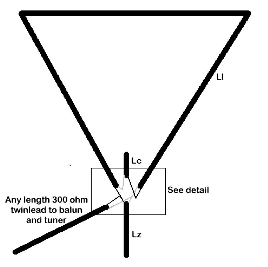
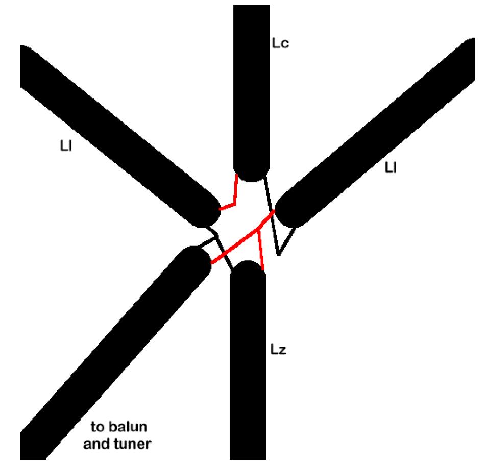
Now this gives you an overall picture of the antenna. Lz has a shorted end, while Lc is left open on the non-connected end. The critical part is in the connections. Each "side" of twinlead is in a different color, and the connections are shown below. The Ll (large loop) connection , properly made, puts a "twist" in the twinlead of 1/2 turn. These diagrams assume that NO twisting is made in the twinlead, and what the resulting connections look like. Use an ohmmeter to ensure you are NOT connecting the same wires! Use heat shrink or other GOOD insulating material -- the voltages and heat can get very very high at the junction points. Good soldered connections are also critical.
Here is the detail of the connections:
Why, if the antenna is resonant, is a tuner required? Well, it's not. But your usable bandwidth (2:1 swr points) is pretty narrow, at 1/100th of the design frequency. So, adding a tuner stretches it out a bit, in a fairly reasonable fashion. I have had no trouble with a Kenwood AT-50 in covering the entire 40 meter band. If your tuner requires a 50 ohm coaxial input (like mine does) you can use a 6:1 balun in line.
The open capacitive stub of 6" will raise the resonance point approximately 100 kHz for 80/75 meters.
Here are the formulas:
The total length (Ll and Lz, or Lt) = 130 /
F(MHz)
The shorted stub (Lz) = 27 / [(2xF(MHz))-2]
Loop length (Ll) = Lt-Lz
Capacitive tuning stub (Lc) = 24 x (1 / [F(MHz)/2]**2) (Note: Capacitive stub becomes pretty useless above 30m, in fact the whole antenna gets pretty darn small!)
Remember, adding the capacitive stub lowers the resonant frequency!
Play around with it. I have one on 40m, and I love it. Make no mistake. Contesters have used this antenna effectively! This isn't an antenna for sissies ...
Here are some pre-calculated dimensions. Remember that the total loop length can be divided by three (in a delta configuration) or four (in a square configuration) to give you an idea on space required.
| Band | Freq. | Lt | Lz | Ll | Lc (to lower resonant freq. by 100 kHz) |
| 160 | 2.0 | 65' 0" | 13' 6" | 51' 6" | 24" |
| 75 | 4.0 | 32' 6" | 4' 6" | 28' 0" | 6" |
| 40 | 7.3 | 17' 10" | 2' 2" | 15' 8" | 1 3/8" |
| 30 | 10.15 | 12' 10" | 1' 6" | 11' 4" | 1" |
| 20 | 14.44 | 9' 0" | 1' 0" | 8' | 1/2" |
Full-wave Loop
Think you don't have much room for an antenna? Don't forget about the Full-size 10 meter loop. At 8' or so per side, most antenna restricted amateurs can use an indoor or balcony mounted 10m loop. The formula is widely available, with the total circumference = 1005 / f(MHz). The challenge is that a full-wave loop has a feedpoint impedence (either horizontal or vertical) of about 100 ohms. 2:1 baluns (needed to use 50-ohm coaxial feedline) are hard to find. The ARRL Antenna Book suggests using 1/4 wavelength of 72-ohm coaxial cable (such as is used for CATV installations, or connections between TV/VCRs), as a direct feed to the loop. This tranforms the impedence to 50 ohms.
Don't forget, too, that radiation is perpendicular to the plane of the loop. A horizontal loop is truly a "cloud warmer", as the radiation is almost straight up. Hung vertically, the antenna becomes pretty directive (side nulls) but puts a really low angle of radiation to the sky. Think about the directivity before installing, if you have some options. In my case, I oriented it at my Tennessee QTH with the null toward Montana and Wyoming, to pick up New England and "null out" the strong stations I encounter from Georgia, the Carolinas, and Florida.
Full wave loops are pretty usable on lower bands as well, with a tuner. I'd guess you can probably find a good match (with even an automatic tuner) down around 30 or 40 meters from a full-wave 10m loop, with relative efficiency. Well, probably as good as a shortened (loaded) vertical.
Cage Doublet
The final antenna that I have used in my arsenal/antenna farm isn't compact at all, but rather a fat dipole (we called it a Cage Dipole). It is somewhat shorter than a full-sized doublet or dipole.
Why is this a useful antenna? Well, bandwidth is a function of radiator diameter. At 0.064 in. (14 ga. wire), the bandwidth is pretty narrow. Increase that diameter to 8 or 12 inches and you might cover all of 75/80 meters (CW and SSB) within a 2:1 bandwidth. Plus, it gets a bit shorter. The theory is that by increasing diameter size you decrease Q without impacting efficiency (through lowering radiation resistance).
The concept is to have 6 or 8 dipole wires parallel to each other, kept spread apart with a spacer. PVC pipe (an 8" or 12" diameter) with holes drilled through sections provide a good spacing. Every 10-12' or so is adequate spacing. Make sure you drill holes on the appropriate angle to evenly distribute the wire.
You use the pipe and cut it into 3/8 to 1/2" cross sections. Drill the holes through the thickness of the wall, on the correct angle, slightly larger than the wire to be used. We found it easier to use a support (strong, like a tree) to extend the wires while threading the wires into the spacers. Don't worry too much about spacing the spacers exactly. They are there for mechanical support, and placement isn't critical. In fact, we put all of them on one end of the wires, then tied the wires together, THEN spaced them. Work on one side of the doublet (dipole) at a time, and BE PATIENT! At 80m this thing can have the cooporative factor of a slinky that has been wound too tight.
A word on type of wire. I found stranded difficult to work with. Solid wire, left alone for a few days with good pressure on both ends will tend to lose the tendency to curl. I found some copper-clad electric fence wire, which worked beautifully.
What about dimensions? My material doesn't have formulas, but a rule of thumb is that the standard dipole formula, less 4% for 8" diameter. A standard 80m dipole, using the 468/f(MHz) formula, is 124.82'. Less 4%, the length of the 8" diameter "cage" dipole is 119.8'. This gives a 2:1 bandwidth of 375 kHz (in practice my bandwidth was a bit bigger). A 12" diameter would be somewhat shorter still, perhaps 5%. Don't be afraid to build it a bit long and trim as needed, just as you might a typical dipole. They are easier to trim than construct!
What is the benefit (other than bandwidth) for this antenna? Well, actually, it appears to exhibit some gain. On recieve the larger capture area appears to be the reason, and on transmit the antenna appears tremendously efficient (resulting in increased signal strength). Higher latitude installations might be aware that this antenna won't generate a lot of heat, so ice loading becomes a concern. Again the copper clad wire helps.
Overall construction:

Detail of spreader:

Return to The Curmudgeon's Corner
This page, and all original graphics, © 1996, Martin D. Watt.