N5ESE Builds (and Mods) the Elenco XP-720 Bench Power Supply
(click on any image to see a larger version)
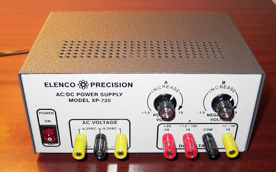
Here's a old-timey kit, with excellent up-to-date applicability. The Elenco Model XP-720 or XP-720K KIT provides a bench-type power supply with triple DC outputs of +/- 20V (adjustable) at 1 Amp, and +5 V (fixed) at 3 Amps. All three outputs are linearly regulated using three-terminasl IC regulators, with the +5 VDC output supplemented with a PNP pass transistor. All this for a very reasonable $60-65.
Construction
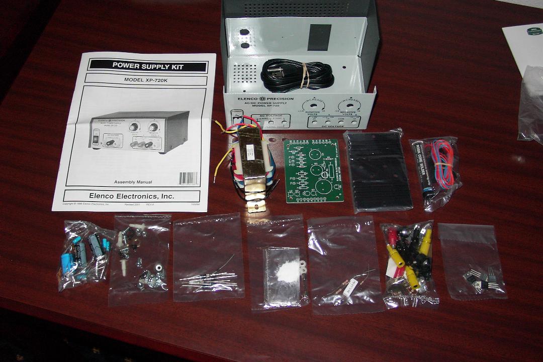
Building this kit saves you about $50, and that's reason enough to get the kit, but mostly you'll enjoy a couple of very enjoyable evenings of old-fashioned kit-assembly. I say old-fashioned, because the kit reminded me of an old Heathkit.
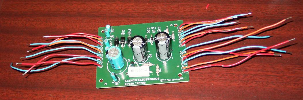
The pc board is single-sided, something you rarely see in modern kits. And they even supply the solder! Here's a view of the board, completed, and just prior to installation in the chassis.
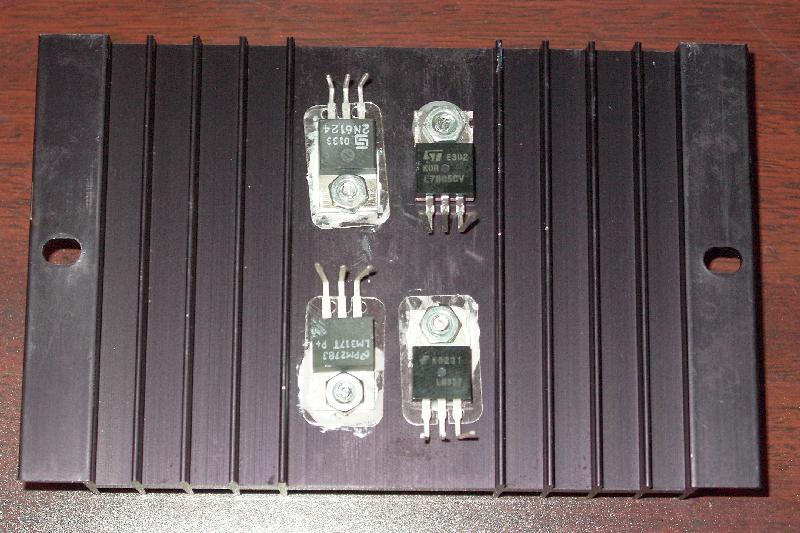
The three-terminal regulator IC's and pass transistor, all TO-220 packages, mount to a black-anodized heatsink, sized to dissipate about 20-25 watts. Take a gander:
Controls and connectors are panel-mounted (not board mounted), with lots of manually soldered wires between the board and controls and chassis-mounted parts. The chassis is of the double-U type, about 6x8x4"H, and precisely pre-punched with a professional silkscreen and hammertone finish. Here's a picture of the inside view, assembly completed:
First Round Modifications
There are no RF decoupling capacitors in the circuit, and since we do mainly RF homebrewing, we thought these would be cheap insurance. So we added 0.01 uF and 0.001 uF disc ceramic capacitors at various spots throughout the power supply. Also, we tied the center pin of each control potentiometer to the adjacent unused pin. This prevents the potentiometer from going "open circuit" to the regulator's feedback pin, if the potentiometer gets dirty with age (it's a carbon pot).
Observations
After double-checking my wiring, and checking for no-shorts at the output pins, we plugged the power supply in, and flipped the front-panel switch "ON". A quick voltmeter check at the outputs confirmed all was working. The two adjustable outputs were quite smoothly adjustable from 1.25 - 20 Volts (and from -1.25 to -20 Volts). After momentarily shorting the outputs (on purpose), the output voltages returned immediately to their preset regulated values.
Second Round Modifications
We got tired of hanging the DVM on the output everytime we wanted to know what the output voltage was, or how much current the load circuit was drawing. There is a lot of open space in the power supply chassis, and a pretty big hunk of unused front panel at the upper left (well, actually, the logo silkscreen is there). So I figured, why not put a digital panel meter (DPM) in the unit?
The XP-720 has 3 DC power supplies in it, and only 2 are adjustable. It would be rare that I breadboard with all three power supplies, or with the +5 Volt supply alone, and there would be little need to monitor the +5V supply, so for simplicity's sake, we decided to switch the DPM so as to monitor either the current or the voltage on either the positive or the negative adjustable supply.
Digital Panel Meters come in two basic flavors: those that run from 5 Volts and share a common ground (at the input) with their 5 Volt supply, and those that run on an independent 9 Volt battery. We decided on the latter, because then we could have our DPM's differential inputs connect independently of the grounding system in the power supply. The 9-Volt DPMs only draw about 2 mA, but that's still enough to drain a 9 Volt battery (albeit slowly), so we decided that we needed an automatic way to connect and disconnect the 9 V battery.
Here's a schematic:
U2 is an optocoupler with bipolar MOSFET-type outputs. When U2's internal LED is dark, the FETs at the output are OFF, and the 9-Volt battery is essentially disconnected. Applying AC-power to the XP-720 power supply causes the fixed voltage +5 VDC supply to forward bias U2's internal LED, causing the output FETs to turn on, connecting the 9V battery to the DPM (with about 35 ohms of ON-Resistance).
Two switches control the operation of the DPM. Switch S1 determines if the positive or negative supply is being monitored, and switch S2 if current or voltage is being monitored. Our DPM has a single range (+/- 200 mV, actually +/- 199.9 mV), so we need a voltage divider to knock our supply voltage down to that range. With the values of R2, R3, and R4 shown, the full scale of the DPM (i.e., 200 mV) represents 20 Volts. One section of the 'Volts/Amps' switch S2 controls the placement of the decimal point on the DPM, and also controls whether "V" or "A" is activated on the meter. By the way, the meter is auto-polarity capable, and will automatically indicate a negative sign if appropriate. As wired, the meter reads -19.99 to +19.99 Volts, and 0 to +1.999 Amps (we don't expect current flowing into the meter). This gives us resolution of 10 mV in setting the two adjustable power supplies, and resolution of 1 mA in measuring current. Trim pot R3 allows us to calibrate the DPM. I did this by turning the positive power supply up to max voltage (about 19.95 Volts), and adjusting R3 to make the DPM match my handheld DVM.
A word or two about the current sense resistors. These are precision 0.10 ohm wirewound resistors. I used 3-watt resistors because that's what my supplier had in stock. Anything 1-watt or above will work. Applying Ohm's Law, you can see that 2 amps times 0.10-ohms equals 0.2 Volts, which is the full scale range of our DPM. Perfect! The XP-720 power supply uses a three-terminal regulator in each of the adjustable supplies. A voltage divider in the output of each supply taps a small portion of the output voltage to be fed back to the 'ADJ' terminal of the regulator. The regulator then turns on it's internal pass transistor (or turns it off) as necessary to maintain the correct voltage at the 'ADJ' pin. As originally assembled, the V-OUT pin of the regulator goes directly to the top of the voltage divider, then to the output terminal (on the front panel). We will break that circuit, and insert the sense resistor between the V-OUT pin of the regulator and the top of the voltage divider. If switch S2 is positioned in "AMPS", the voltage across the selected sense resistor (positive or negative supply) is routed to the input pins of the DPM. The DPM reads 0-199.9mV, but displays 0-1.999 Amps. Note that because the current sense resistor is installed before the feedback voltage divider, the current in the voltage divider will be included in the display. At 12 Volts, this is typically about 10mA. With no load connected, we can read that value directly off the DPM. So to get an accurate reading on the current in our external test circuit, we remember to subtract the voltage divider current from the DPM's indicated value.
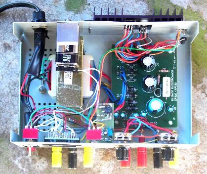
In constructing our DPM addition, we needed to find a place for some stuff inside the cabinet of the XP-720. The DPM and two switches installed on the front panel, upper left quadrant. Here's a picture of that:
There was some space above the main transformer for the 9 Volt battery, so we mounted a metal clip on the inside rear panel in that area, to hold the 9V battery in place. To mount the two current sense resistors, we mounted a 5-terminal strip (of the old-fashioned phenolic & solder lug variety) to the inside rear panel. For resistors R1 - R4 and the opto-coupler U2, we fabricated a small 1-in x 2-in pc board, using cut-and-peel techniques, and mounted it to the inside front panel. For all wiring except the sense resistors, we used some colored ribbon cable, AWG 30 stranded, stripping off what we needed one wire color at a time. For the sense resistors, we used AWG 20 hookup wire.
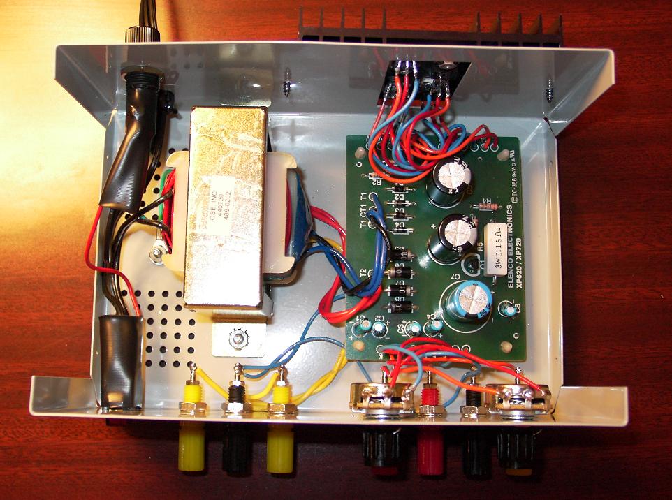
The inside view of the power supply is a lot busier after the mods for the DPM:
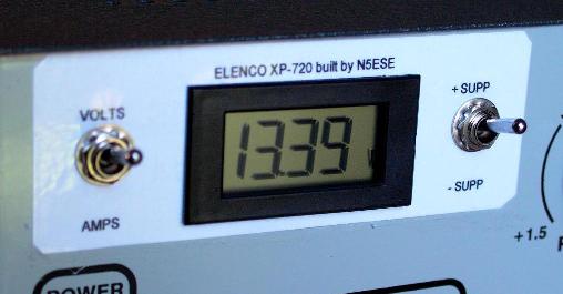
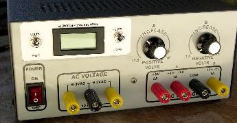
and here's an overall view of the front panel, with display:
Conclusion
I like this one! I frequently have a need for a variable supply when testing homebrew circuits, and the triple power supply is just what I need on the bench. With an amp out at 13.5 V, it will easily handle that QRP full-gallon. It even has 6 and 12 V AC available, for those rare filament-power circuits (what are those called, again?). Don't know how long this kit will be around, but I highly recommend it.
The Digital Panel Meter is a pure luxury. Cost for new parts for the DPM mod would be around $50, but I only had to buy the 3PDT switches at $6/each and the sense resistors at $2/each, because I had picked up a $3 panel meter at a recent swapfest, and the rest of the parts were already in my junkbox.
73,
Monty N5ESE
dit dididit dit