N5ESE's Version of KA8MAV's Tiny-Tornado Kit

(click on any image to see a larger version)

| NOTE: 'N5FC' is my former call. This project was constructed while that call was valid, and you may observe references to it. |
The Tiny-Tornado is another low-cost, fixed frequency CW QRP trasceiver kit. Based on the well-known PIXIE II design, it was refined and re-designed by Brice Hornbeck, KA8MAV in the finest minimalist tradition. It demonstrates that a workable QRP rig can be built using the fewest components possible, in the smallest space possible. In fact, the rig uses two transistors and one audio IC to accomplish the entire task. And even though the unit uses through-hole construction, Brice has managed to package it all onto a printed circuit board with a footprint of less than 2 square inches! Priced at $34, it was darn near impossible for me not to order one. Unfortunately, they were a limited-edition run. To get the full low-down on the kit, including schematics and manuals, see
Even if the rig is unavailable in kit form, it's so simple and uses such readily available parts, that it would be a cinch to homebrew from scratch. For most parts, you can order online from your favorite supplier (mine are Mouser and Digikey). For low cost, standard QRP frequency crystals (which are becoming more and more difficult to source), check AF4K Crystals, and Expanded Spectrum Systems
Construction
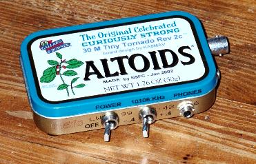
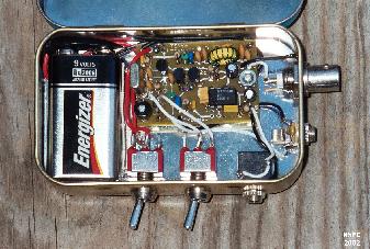
As I am frequently inclined to do, I decided to see what I could fit entirely inside an Altoids Tin. My personal experience is what I'll describe here. In fact, I was able to install both the Tiny-Tornado and a 9 Volt battery inside the case. Two toggle switches, two mini- jacks, and a BNC connector round out the build. Here's a view with the cover open:
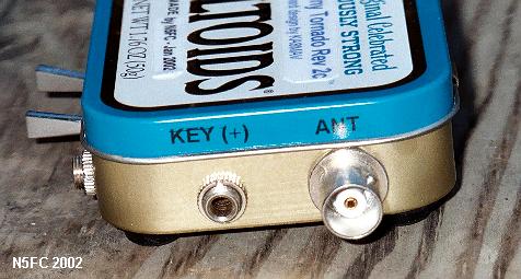
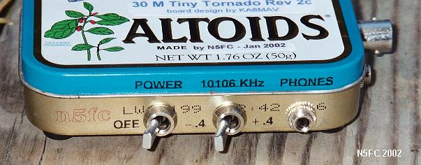
The leftmost toggle switch turns the 9 Volt power on and off. The next switch reverses the offset of the fixed frequency oscillator, which in this case was set by the 10.106 MHz crystal (other bands were available). This way, you don't get stuck zero-beat with your QSO partner. Receiver audio for stereo headphones is available at the mini-jack. The next mini-jack (adjacent to the BNC) is for the key input, and of course the BNC is for connecting to the antenna or antenna tuner. Here are the side views:
Documentation provided was more than adequate for assembly, and mine went together in a single day, including packaging it into the Altoids box.
Modifications
I put a couple of mods into my unit:
2. I changed C15 from 1000 pF to 8.2 pF. This gave me a 850 Hz "offset" when the crystal oscillator was trimmed to 10106 KHz. I'm guessing the value of C15 will vary a lot, unit-to-unit, because the amount of pull possible depends a lot on the individual crystal characteristics.
I did observe a tendency toward instability during some load conditions. In my experience, this is not unusual for minimalist rigs, but it does require attention on the part of the builder/operator. In my unit, when operated into a dummy load, or into an antenna using the Emtech ZM-2 antenna tuner, SWR was fine. When operated into a the same antennas using my MFJ-971 tuner, even when preadjusted to 50 ohms, SWR was near infinite and could not be adjusted. I suspect some kind of off-frequency oscillation in the final, but I can't guess what the specific cause of the instability might be.
Operating rockbound on both RX and TX is an interesting, but not entirely pleasant experience. Fortunately, I added the switch to provide an "offset", but since there is no automatic T/R switching (of the offset), that meant I needed to manually switch it from TX to RX to TX each time. I lost one guy when I forgot to switch back to the TX freq.
Hum in the DC receiver was also a problem for me. I finally discovered that the level of hum was related to which of three antennas I was using, and which of the unused ones I had grounded and ungrounded. I finally found a combination that was usable. Also, I could reduce the effect somewhat by adding 5 or 10 dB of attenuation in line with the antenna, but of course, that was another switch to throw when going from TX to RX HI HI. To make matters worse, receiver gain, though adequate, is fixed, and tends to fool you into thinking a moderately strong station is weak, especially in the presence of the hum.
Following are some observations and measurements I made on my unit. Keep in mind the TX has 2 parallel transistors, rather than the stock single transistor.
Shortcomings aside, the rig proves its point, and very well: a minimalist approach, while discarding features, will still get QSOs, and a kit built around this approach can be a load of fun to build and operate. Hats off to Brice KA8MAV for offering this fun kit!
But Does It Work?
I couldn't raise lint from felt on the first night I tried, but I snagged two Q's the following morning on 30 Meters. A 29 minute QSO with John KC0HQU in Joplin, MO, 503 miles, for 1250 miles/watt, was the best dx. That time, I was running QRO (wink) from 12 VDC at 390 mW out.
Another ragchew QSO with Dale KD5YSJ in San Antonio proves it can be done with only a 9 Volt battery, yielding 200 milliwatts.
73,

(click on any image to see a larger version)

1. For Q2, I used 2 parallel PN2222's with 2.2 ohms 1/8-watt emitter ballast each; this almost doubles the power output. I matched the transistors for hfe. Turns out the PC board's holes are big enough to take two leads in one hole. No extra heat sinking was needed (they never even get warm to the touch). The instructions say to decouple the ballast resistors when paralleling transistors, but I believe this to be unnecessary, and maybe even counterproductive. Commercial emitter-ballasted RF transistors never have decoupling.
Observations
Receiver Current Drain:  9.3 mA @ 9 VDC, 14.5 mA @ 12.6 VDC
Transmit Current Drain:  52 mA @ 9 VDC, 87 mA @ 12.6 VDC
Transmit Power Out (2 x 2n2222's):  200 mW @ 9 VDC, 390 mW @ 12.6 VDC
Receiver backwave:  5 mW @ 9 VDC, 6 mW @ 12.6 VDC (hmmm...)
Receiver MDS:  approx 0.4 microvolts (measured)
Receiver Blocking:  begins at 600 microvolts (and it ain't pretty from there on up)
Monty N5ESE
dit dididit dit
Overseer: Monty Northrup ...
![]() ... leave e-mail ...
... leave e-mail ...