(click on any picture to see larger version)
Well, Steve "Melt Solder" Weber, KD1JV, has nailed me again with yet another kit I have to label as "indispensable". Here's a poor man's ($25) SWR anlayzer that fits inside an Altoids box, 9-Volt battery and all. It's currently distributed by the Four State QRP Group.
What's an SWR analyzer? Basically, it's an SWR bridge with a wide-range oscillator built into it, and an indicator for reading the SWR. They're great tools for adjusting antennas in the field (or at home). You can also use them for pre-tuning your antenna tuner, without transmitting. For portable QRP ops and backpacking, where size and weight make a difference, the commercial SWR analyzers are pretty cumbersome and heavy. Enter the KD1JV "Tenna Dipper".
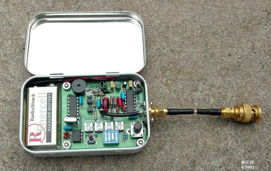
The Tenna Dipper is a small PCB (about 2 x 2 inches) that will fit inside an Altoids tin (or the box of your choice) along with a battery. It contains a wide-range oscillator, based on an RC tuned VCO provided as part of a common CMOS PLL chip. When operated at 6 volts, Steve manages to eek out 2-40 MHz oscillations, all controlled by a bank of tiny pots. Which pot is selected is determined in part by a "Hi-LO" DIP Jumper, and in part by a four-position DIP switch. An additional pot provides a "fine-tune" control. Properly set up, one is able to select any of the HF ham bands, and tune across them in their entirety. So that you know where you're tuning, Steve included an audible CW annunciator for the frequency.
The oscillator feeds one branch of a 50-ohm resistive bridge (actually, 51 ohms, as supplied). The unknown load (i.e., the antenna, antenna feedline, or tuner) is connected to the opposite port. A darlington pair provides detection and drives an LED, which serves as our relative SWR indicator. When unbalanced, the LED is brightly lit. As the unknown load approaches 50 ohms (or - said another way - as the SWR gets lower), the LED gets dimmer, until at 50 ohms, the LED goes completely out (corresponding to a 1:1 SWR). How many times have you wished for something like this in the field, without risking your finals and causing QRM?
CONSTRUCTION
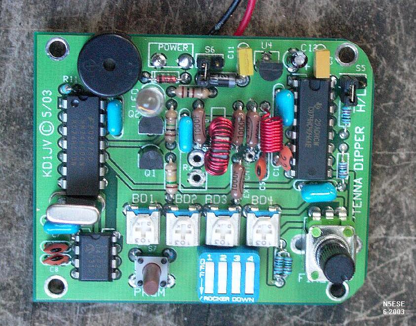
Steve says that if you're going to mount this in an Altoids tin, along with a battery, be sure to round the right-most corners first. I did just that. Construction was straightforward. Although it was necessary to cut a trace on the supplied printed circuit board and make a repair to it, the instructions for doing so were quite clear, and it was done quite easily. Parts are all through-hole, so you surface-mount-phobics can relax (sheesh!)
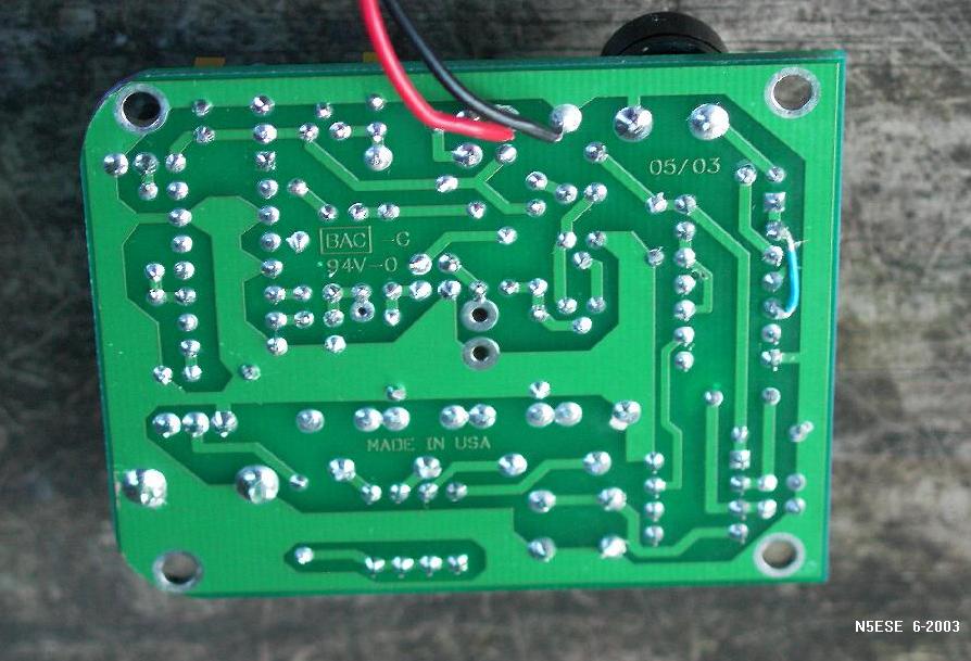
Here's a picture of the top side of the finished PCB (before installing it in the Altoids tin), followed by a picture of the bottom side:
Unfortunately, there really isn't room to mount a BNC connector on the Altoids box, if you install both the PCB and the battery inside. SMA connectors are smaller, and I managed to squeeze one in, but that requires that I use a series of adapters to go from SMA to my equipment, which all has BNC connectors. Of course, this works fine, but adds to the expense unless you happen to have some in the junk box, like I did. Steve recommends a pigtail of RG-174 terminated by a BNC plug. This will work splendidly, and only the aesthetics kept me from doing that. Keep the pigtail as short as possible, however - certainly, not more than 3 inches long.
Here's a picture of the board installed in the Altoids tin:
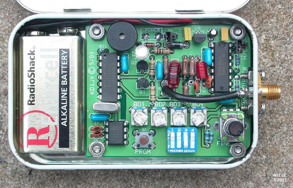
You might notice that I used 2 parallel 100-ohm 1% metal film resistors in place of the supplied 51-ohm resistors (for the bridge circuit). I wanted to feel confident that my bridge was really 50 ohms, and not 48-54 ohms (which is 51 =/- 5%, as supplied in the kit). As supplied, the errors amount to an error of 1.1:1 vs 1:1 SWR, which is negligible for all practical purposes, but it can make the match point appear at a different tuner setting or frequency, which can be disconcerting. I opted for precision.
Operation and Results
I found there were two ways to use the Tenna Dipper in the field. First, to find the resonance of an antenna, one can adjust the frequency using the fine-tuning pot until the LED goes out. This presupposes that the antenna impedance is somewhere near 50 ohms already (say, 25-75 ohms). For example, if one had a wire vertical cut to about 1/4-wave, with at least one radial cut to near 1/4-wave, one could reasonably expect to find the resonance of the vertical. Having found it was low or high in frequency, you would know if you needed to adjust the wire length to achieve the desired resonant frequency.
The second way to use the Tenna Dipper is as a surrogate transmitter for adjusting your antenna tuner in the field. This is the way I most often used it, and the mode I find most useful. To do this, remove the cable from the rear of your field transmitter, and place it on the Tenna Dipper. Adjust the Dipper's frequency to your favorite mid-band operating frequency. Then tweak the controls on your Antenna Tuner until you get the LED to go out. Take your time - no finals to burn out - and fool with the tuner settings or antenna orientation all you want. Once you have it dipped, remove the cable from the Tenna Dipper, attach it to your Transmitter, and fire away (you're matched!).
As one might expect with a $25 instrument, there are some limitations that one should be aware of. Obviously, an LED is a crude SWR "meter". When it's out, you know it's close to 1:1, and when it's brightly lit you know it's not. But in-between, you really don't know much about the SWR. My observation was that the response of the detector/LED was somewhat frequency dependent. Partly, this is because of the bridge and detector response, and partly because the source oscillator output falls off with frequency. At the lower frequencies (80 Meters), I observed that the LED stayed brightly lit until the SWR was down to 1.2:1 or 1.3:1, at which point it would begin to dim. At the higher frequencies (10 Meters), I observed that the LED began to dim at SWRs near 2:1, and would go completely out at about 1.5:1.
When using it on Field Day recently, it proved to be a very useful field instrument for adjusting the antenna tuner using various feedline and antenna configurations. All of this could have been done with an SWR meter and transmitter, of course, but I felt less rushed doing it with the Tenna Dipper. And, of course, I was causing no QRM to the contesters which occupied the band from edge-to-edge. We did encounter one anomaly when trying to tune for 10 Meters. The Tenna Dipper's frequency was indicating about 300 KHz low when tuning into the lower CW segment of 10 meters. I suspect the oscillator's output level was not high enough to adequately trigger the built-in PIC-based frequency counter, but I will have to investigate this further. For all bands tried below 10 meters (80/40/30/20/15), the SWR found with the Tenna Dipper agreed with the SWR on our MFJ-971 tuner when we finally applied transmit power.
73,
Monty N5ESE
dit dididit dit