N5ESE's
The Art of Scrounging
(click on any picture to see larger version)
(click on any picture to see larger version)
| NOTE: 'N5FC' is my former call. This article was written while that call was valid, and you may observe references to it. |
Hams (radio amateurs) have always valued parts scrounged from old, dead, or obsolete electronic equipment. When I was a teenager (in the 60's) getting started in ham radio, the discarded television was viewed as a goldmine... armed with a Weller soldering gun, you could strip countless RF parts, resistors, and capacitors from the chassis, not to mention the tubes and - the prize - a big honkin' power transformer. The old AC/DC tabletop radios gave up their variable capacitors and IF transformers, and war surplus gear was abundant and cheap, and contained primo-quality RF parts and tubes.
I've noticed in recent years that part-scrounging is often considered a "dead art". Maybe it's because hams don't like to "homebrew", or maybe it results from the impression a lot of hams have that there are no usable parts in scrap electronics. Well. QRPers love to homebrew, and as a counterpoint to frequent misgivings, I'll present my own recent experience with modern parts scrounging.
This all came about when a business customer upgraded to high-speed modems, and directed that the old modems be disposed of "in the trash". To an old parts scrounger like myself, "in the trash" translates exactly to "it's all yours". So, I found myself with about 20 commercial-grade modems, of the 19.6 Kbaud variety... too slow for dial-up internet... and in fact, they have no salvage value at all (and somebody may charge you to take them away).
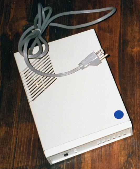
So, let's pop the top off and see what's inside. There were two different models, one of which is shown below, pre-surgery:
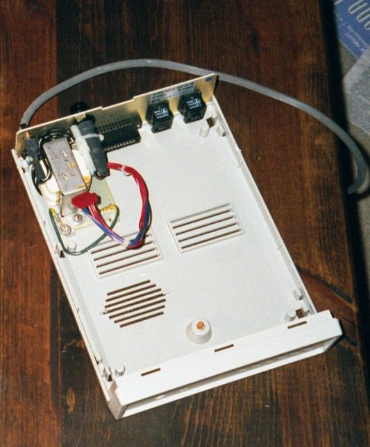
On the left, we see an image of the modem "as is", before we start hacking on it. A few twists of a large common screwcriver in the right slots, releases the plastic cover and exposes the inside. In the image at right, we've removed the printed circuit board and set it aside to be dismatled later. What's left is the first cache of goodies: a 115VAC power transformer, with 35V center-tapped output, about 15 VA. The transformer is split-bobbin wound, so we can easily remove the secondary and wind our own custom winding if we want to. Also seen in the image is the power cord, a high-quality 3-conductor type, its strain relief, a high-quality panel-mount fuseholder for 1-1/4" fuses, and a really nice SPDT mini-toggle switch rated at 250VAC. Most of the stuff we remove with a pair of pliers and some wire cutters, and put them in the "save" box. The transformer is mounted with aluminum pop-rivets, which we drill out in short order. Already, we've made a pretty good haul... but wait, there's more...
The printed-circuit board is chocked full of components, but is there anything the QRP homebrewer can use? You bet! Here's the philosophy we approached this with: I'm not going to remove every part, only what's easy to remove and what I think I might use. The rest is simply not worth my trouble. Also, I'm not going to remove each part with tedious care; this is junque, and if I'm careless and break a part while removing it, who cares? There's more where that came from. I vow to spend no more than one hour removing parts from the board, and in fact I spent less than 3/4 of that. We warmed up the soldering iron a little hotter than usual (about 370 deg C), and went looking for the goodies.
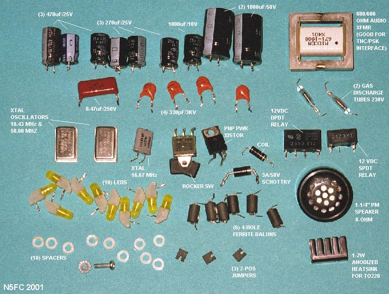
At the end of our desoldering session, we had a mess of goodies, as shown in the image below. Click on the image to see a larger image, annotated to show what the individual parts are. Or click the link below to see a detailed list in tabular form.
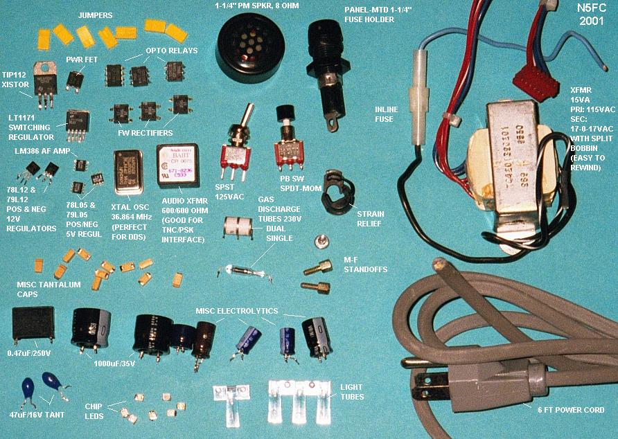
Click on the image above to see a larger, annotated image
Click - here - to see a tabular list of the parts
There are some real treasures here, in addition to a useful array of genereal-purpose parts for homebrewing. Most modems have some kind of surge protection at the telephone line (it's required for FCC-type-acceptance). These had one ceramic dual-cell gas discharge tube (230 V) and one glass-bodied gas discharge tube (also 230 V). These are great for lightning and static protection on balanced feeders, and will cost you $12-15 each if you can find a supplier. Wow! Also scrounged was a 34 MHz metal-can CMOS oscillator, perfect for that DDS project (I'll use mine with an AD9835 DDS chip I acquired some time ago). That would set you back another $10-20 new. There were four low-power linear 3-terminal regulators of various voltages, and lots of aluminum and tantalum electrolytic capacitors, some radial-mounted, and some surface mounted. There was a MOSFET power transistor (good for keying and/or power regulation circuits), and a couple of solid-state relays (the opto-coupled kind). There was even a venerable LM386 Audio Amp and some op amps. Been looking for a transformer for your sound-card to transceiver interface? There was one in this modem
And those were just the parts I wanted. There were lots of digital goodies onboard, and some pretty expensive parts. There was a 66 MHz 56002 Mostorola DSP, with external very high speed static RAM memory chips (that stuff ain't cheap, folks). The 56000 series DSPs are commonly used in ham radio DSP applications, because the assembler software is available free online. Also, a 68HC302 microcontroller, a high-performance 16-bit processor, with external memory. Of course, you could try to scrounge those, and the best tact would probably be to preheat the board in a pan over low heat on a hotplate (NOT in the kitchen though... remember, lead-based solder is very poisonous), then loosen the large surface-mount DSP chip with a hair-dryer, and slide it off. Then clean the leads with solder-wick. Another method might be to simply hack the board around those pieces, leaving the memory and supporting chips attached, clean up the edges real well, and make your connections to the chips for power and I/O signals. I haven't tried it, but it just might work...
We had another model of modem, too. Below, we have a picture of its printed circuit board before the attack:
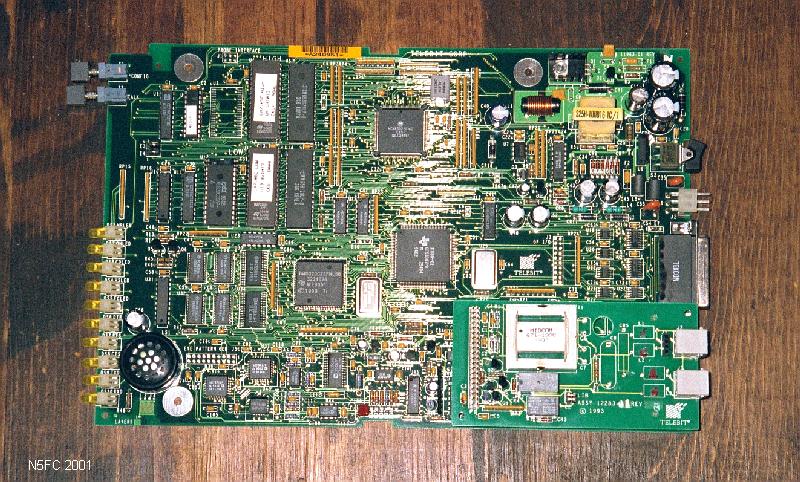
Click on the image above to see a larger, more readable image
Click on the image above to see a larger, annotated image
Like the first modem, this one had two gas discharge tubes in it. This one had two metal-can oscillators, one at 18.43 MHz and one at 50 MHz (ooo-ooo! AD 9850 DDS clock?). And a 16.67 MHz crystal. And besides an array of capacitors, diodes, regulators, op amps, and audio amp, there were several small balun-type ferrite cores, a couple of molded chokes, some push-button switches, and a heavy-duty 600/600-ohm data transformer (for that PSK interface you've been wanting to build). Oh! Did I mention the very high quality miniature PM (not piezo) speakers? For those willing to go to the extra trouble, a 50 MHz TI TMS320C35 DSP with external fast SRAM, an AD7869 A/D chip, and another Motorola 68302 Microcontroller were on board. What a haul!
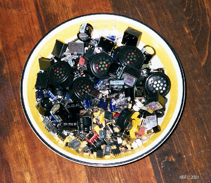
We spent two evenings stripping parts from 8 modems, before we called it quits. There were enough components to fill a serving bowl:
Click on the image above to see a larger, more readable image
Even the plastic cases could be saved and re-used as project boxes, or cut up into QRP antenna insulators. The old hayes-style retail modems had extruded aluminum cases, which to this day are in high demand at swapfests as a project enclosure. Just don't forget about the board-mounted parts.
By the way, we managed to give away a dozen of these modems at the next Austin QRP Club meeting... once people saw the list of parts that came out of them, they realized how easy it would be to build up some homebrew stock. I hope this web page will encourage you to do the same.
Next step: homebrew something!
73,
Monty N5ESE
dit dididit dit