N5ESE builds the
M-Cubed Electronix Semiconductor Analyzer
(click on any picture to see larger version)
(click on any picture to see larger version)
Here's a little gem of a kit I just heard about, and when I did, I wondered how I managed to miss it. This M3 (or M-Cubed) Electronix kit is a first-class semiconductror analyzer (SA) for under $50, which will detect and analyze practical DC parameters for diodes, bipolar, JFET, and MOSFET transistors, and even thyristors and unijunction transistors. Wow!
Do I need to be an engineer to find this useful?
Heck no! ... but if you're an engineer, you will appreciate some of the advanced features.
The SA has a 2-line LCD display, and three "clippy" leads for connecting to your "device under test" (DUT). Aside from a power switch to turn it off, there are no buttons to push. Operation is completely "automagic"
Let's say you have one of those glass diodes, and the markings are so bad that you're not sure which is the banded end. You could grab your trusty VOM, put it in "Diode" mode, and figure it out that way, and hope by the time you get it to the board, you haven't swapped the leads... was that the red or the black lead you had on that end? But clip it on the M3 SA's two outermost leads any old way you want, and the SA's display will show you visually which lead is the cathode (K) and which is the Anode (A), like in the top panel below:
Here, we see that the DUT's cathode is the lead connected to the leftmost clippy, and the anode to the rightmost clippy. Had we connected it the other way, it would have been shown the other way. The diode symbol even helps the beginner remember which is the cathode and the anode, in your schematic. Cool, heh? Theres so much information, in fact, they need to have three LCD panels in succession, at about 5-second intervals, to display it all.
Ever need to match diodes for use in a balanced mixer? The M3 SA can help you do it easily. It will show the forward voltage drops at two different currents, and the leakage current too. In the picture above, the DUT (a 1N34A germanium signal diode, by the way), we see that the Forward Voltage Drop is 0.49V with 10.8 mA applied (panel 1), and 0.27 V with 0.8 mA applied (panel 2), and the Reverse Leakage Current is 0.6uA with 4.94 V applied. Hey, we just discovered a leaky diode!
The M3 SA has enough built-in-capability to handle voltages up to 9 Volts, and test currents up to 12 mA, and enough smarts to interpret the results into useful paramenters. One of the pleasant surprises I discovered was it's capability to screen LEDs. If you've ever homebrewed with LEDs, you know that one lead is just a smidgeon longer, and that lead is the - oops - which was it? No matter, the M3 SA will find out for us:
Let's look at the results above. From the first panel, we see the Cathode (K) and Anode (A) marked, Cathode on the right clippy, anode on the left. But we also see that this LED has a forward Voltage drop of 2.00V with 7.2mA, and 1.80V with 0.54 mA, and little or no leakage current. Knowing the voltage drop is essential to selecting the correct series limiting resistor value to place in the circuit. But wait! There's more, and it's free! While the M3 SA is doing it's diode tests on the LED, it's pulsing said currents through it, and the LED is LIGHTING! So by watching the LED as the SA cycles through the various panels, you can see how bright it's going to be at 7.2 mA and at 0.54 mA, and you can judge what would be a reasonable current for the brightness you want from the LED. This is sooOooo cooOool !
Well, so we know it does a great job on diodes. Lets see what it does with one of those three-legged critters. We grabbed a 2N2222 out of an envelope with about a hundred in it, and hooked up the three clippies, one to each lead of the transistor. It doesn't matter which lead goes to which clippy. The M3 SA is going to figure out which is which and tell us. Here's what we got:
The results show up about a half second after we clipped on the third lead. From the first panel, we see that the M3 SA has identified this as a NPN, probably silicon (Si), and the Hfe measures 172 at a collector current of 2.61 mA. Hfe is the DC current gain, and one of the key parameters you need to know for correctly biasing a transistor. It is especially critical to know when designing cascaded DC-coupled stages. We see here that this transistor is typical for a 2N2222, which is specified to have Hfe in the range 100-200. Chances are this transistor is good in other ways, too. In panel 2, the M3 SA has taken the base current (15.2 uA) used to produce the collector current in panel 1, and has measured the actual Vbe (base-to-emitter voltage, kinda like a diode drop), a parameter which is also needed for bias circuit calculations. Finally, in panel 3, we see the emitter-collector leakage current (with no bias applied). In a good, small signal transistor like the 2N2222, we'd expect to see something less than 1 uA (and we see zero).
The M3 SA can detect shorts and opens in transistors, which are common failure modes when they overheat or otherwise operate outside their safe operating curve. It can also detect a shunt resistor in the base-to-emitter circuit (not sure I've ever seen that in 40 years of electronics) and a protected diode embedded in the collector-emitter, and will so indicate on the display.
Here's what happened when we hooked up a MPF102 transistor to the M3SA:
The SA correctly detected that this is an N-Channel JFET, and correctly identified the leads Gate (G) - Source (S) - Drain (D) from the left clippy to the right clippy. Incidentally, it's practically impossible to differentiate between the Source and the Drain in a junction FET, using an ohmmeter, and the guys a M-Cubed have figured out some slick way to do it reliably. That in itself makes the SA worth the small expense. I can't tell you how many times I've smoked a FET by having the leads wrong. Even all MPF102's are not pinned out the same way, which is extremely annoying to discover after you've been troubleshooting a homebrew circuit unsuccessfully all day long.
In panel 1, the SA also told us that the pinch-off voltage (Vto) is -4.10 V and panel 2 says that the Drain Current with 0 Volts applied is 15.6 mA. By the way, the guys at M-Cubed are showing off again, because they're doing some predictive calculations to come up with that drain current in a tester that can only provide 12 mA. But it's a very useful parameter to have when designing with JFETs. Panel 3 tells us that the Rds-ON (saturated Drain-to-Source On Resistance) is 130 ohms.
The M3 SA can also detect and measure MOSFETs. There are small signal and power mosfets, and the SA can only measure enhancement-mode types. Fortunately, most of what is on the market today are. Lets look at two:
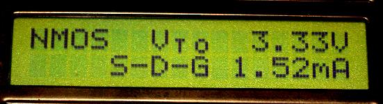
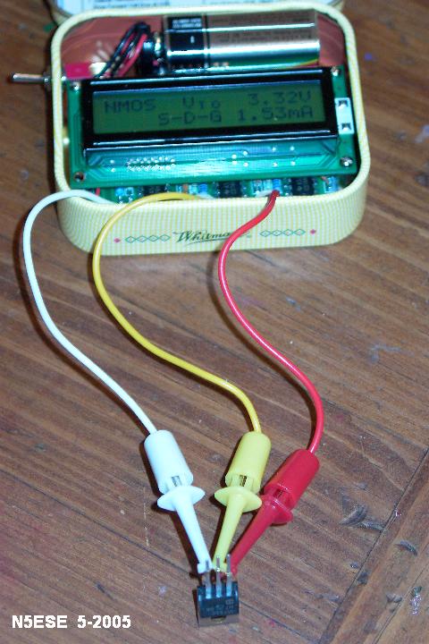
These are both power MOSFETs. MOSFETs generate only one panel with the SA, but one of the most critical pieces of information is on that panel, the Gate Threshold Voltage, Vto. In the top image, the SA correctly identified the leads on our IRF510, and labled it an NMOS device. It then measure the gate threshold volatge as 3.33 Volts, which is pretty typical of this class of transistor. We wouldn't be able to use this transistor in a 5 Volt TTL logic circuit, however, because it wouldn't reliably turn on.
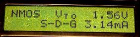
We put another transistor on, the MTD3055EL, and discovered it would indeed be suitable for TTL logic circuitry. As seen in the second image above, its gate threshold voltage is 1.56.
There is a critical parameter missing on the MOSFET panels, Rds-ON. I found it curious that the same parameter would be shown for JFETs, but not for MOSFETs, especially considering it is a much more critical parameter in power MOSFET devices. I asked M-Cubed about it and was told that it was left out because they had no more program space in the PIC microcontroller they were using to do that calculation and display it. Hmmm. Oh, well, one minor shortcoming amongst a mountain of features.
We didn't examine some of the capabilities of the M3 SA, because I didn't have some of these devices in my junk box: SCRs, Triacs, and Unijunction Transistors. Unijunctions? I haven't seen one in the flesh since about 1975, and even then they were an oddity. The SA is also capable of measuring current transfer ratio on an optocoupler, with the addition of an option module. You'll have to ask M-Cubed about that little feature.
Building the M3 SA
For $6, you can get a plastic utility box with all the holes (including the LCD rectangular window) already nicely milled out for you. In fact, I got it. Good Price, and should really simplify construction.
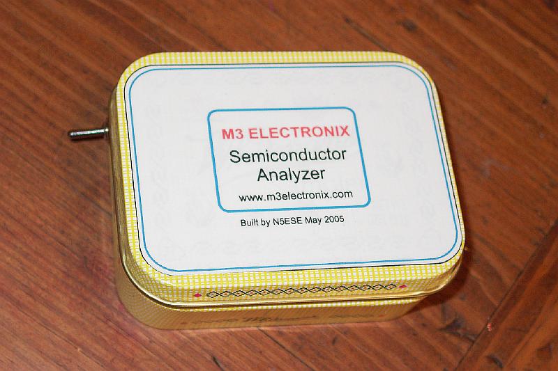
But any of you that follow my homebrewing pursuits know me better than that. If it'll fit in an Altoids tin, that's where it's gonna go. Well, this one wouldn't, but it would fit in a Whitman's Sampler tin - HI HI - which is about a tenth of an inch deeper and half an inch wider, front-to-back. I'd have to do some drilling and filing to fit it in there, but that won't stop me from indulging my addiction for candy tins (and candy).
I sat down and played with the main PC board and display for a while to see what had to be done to fit it in the can. M-Cubed pretty much expected the LCD to mount to the front panel at 4 points using hardware provided. I didn't want to cut a rectangular hole in the super-thin sheet metal of the sampler tin, so I opted to mount the LCD display to the main pc board. Trouble is, there were no holes on the main pcb for doing that. So I made three: top-left, top-right, and bottom right, to match the display mounting holes. In the process, I drilled through 2 traces, which I cut back from the mounting hole, and repaired with a short piece of kynar-covered wire-wrap wire.
I also rounded the bottom-left and bottom-right corners of the main pc board. That allowed the main pc board to be moved closer to the front side of the sampler tin, giving me just enough room behind it to install the power switch and the 9-Volt battery. I substituted a micro-toggle switch for the toggle switch provided in the kit, to assure there was room for the battery and its wiring.
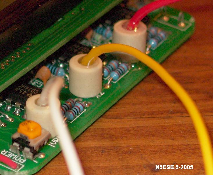
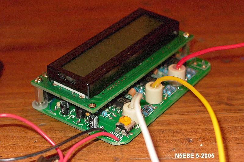
One weakness that was mentioned by the supplier was that the leads needed some sort of strain relief. The test leads are made from common hook-up wire, with 7-stranded copper wire and PVC insulation, so it wouldn't take long before metal fatigue set it and one of the leads broke at the solder joint. M-Cubed suggested hot glue, but after a short but furious rabble through the garage, I gave up on that idea. Instead, I got three short ceramic standoffs from the junk box, and super-glued them over the lead's holes in the pc board. Then I soldered the leads in place, so that they stuck straight out of the ceramic spacer. I then mixed up some 5-minute clear epoxy (which I find is a great electrical potting compound), and filled the spacers with the epoxy, forming what I think is a very durable lead arrangement. See the picture below:
Below is a picture of the overall assembly, before installing it into the Whitman's Sampler tin. The LCD display is held rigidly to the main pc board using 3 threaded spacers and 2-56 hardware, with a nylon washer to protect the main board where the spacer mates to it.
Finally, here are two pictures showing it's installation into the tin:
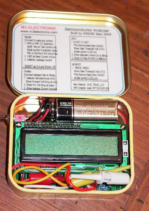
The pc board mounts directly to the bottom of the tin, using some 3-M double-sided foam tape. I made sure to clip all the leads on the bottom of the board very close with my flush-cutting dikes.
See, it really does fit! Even the leads fit inside the tin, protected from whatever corner of the bench I threw it in last. When I want to measure a transistor or diode, I just flip the top open, flip the power switchto ON, pull the leads out, and have at it!
Conclusions
This kit is a real value, not only for it's reasonable price, but for its utility on the bench too. This is really going to go a long way toward taking those random uncertainties out of homebrewing and kit-building.
73,
monty N5ESE