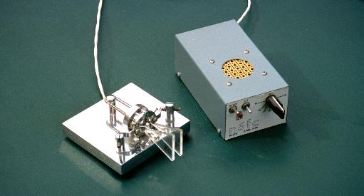
N5ESE's Iambic Keyer

CMOS construction
by Monty Northrup, N5ESE

CMOS construction
by Monty Northrup, N5ESE
| NOTE: 'N5FC' is my former call. This project was constructed while that call was valid, and you may observe references to it. |
Nowadays a keyer makes a relatively simple homebrew project. For less than $20, the TICK single-chip keyer is probably the most popular, requiring only a handful of external parts to accomplish an iambic-paddle-type keyer. Similar in simplicity and popularity, for about the same price, is a PIC-based keyer, by K1EL, also available in kit form. FAR Circuits has printed circuit boards for both Curtis and PIC keyers, among others.
I enjoy building from scratch, and I wanted to build a discrete-logic-type circuit using CMOS chips. The 4000-series CMOS chips had several compelling features: negligible quiescent current, relatively slow risetimes/falltimes, operational from 3-15 volts, and very cheap. The circuit outlined here was updated from a QST article by James Garrett, WB4VVF, published in August 1973, and dubbed the "Accukeyer". Thje original circuit was based in 7400 TTL technology, and this circuit updates it to HCMOS, and adds some features. The core circuitry remains essentially the same, but we've added input protection (to guard against human-static-discharge at the key-paddle), a voltage regulator (so that the speed control remains the same regardless of battery condition), a battery-monitor circuit (with LED to tell when the battery is nearing end-of-life), and power-MOSFET keying (for better battery life and better key-down dynamics).
The entire unit is packaged in a U-type enclosure. I elected to use sockets and component headers wherever possible, wire-wrapping where I could. In the schematic, you'll see numerous references to "Hn-p"; for example H5-13 means "Header 5 - pin 13".
RF susceptability is negligible, in part because of the liberal use of ceramic decoupling capacitors (most not shown on schematic... I usually put one 0.01uF across each IC, V+ to Gnd). One of the really nice features that took some getting used to was the "Autospace" function, which is switch selectable. When ON, it assures that a full "space" is inserted between letters, greatly reducing the possibility of run-on sending. Sidetone can be turned off-and-on as needed (most of the time I don't need it). I've had the unit in service for about 4 years, and although I have a power switch on it, I usually forget and leave it ON. Still, I've only changed the 9V alkaline battery once in that time. You could easily save parts by eliminating the battery monitor (a dubious luxury) and regulator circuit (whose main function is to keep the speed predictably settable on the front-panel dial).
Be sure to check out the following images. I apoligize for the quality of the scanned drawings, which are poor in spots, but still quite readable. In order to pick up the detail (in the drawings), I scanned at fairly high resolutions, then converted to .jpeg files. You can view them on your monitor if you have a fairly high-res model, but most will want to print them from a graphics viewer. Usually, this can be done by right-clicking on the open image, then saving it as a file in a directory/folder of your choosing, and then opening it with your graphics viewing software. HTML browsers (like Internet Explorer and Netscape) are terrible at printing large graphics files, and refuse to scale them under user control, but the graphics programs do a good job of it. In your viewer's options, select to scale to page size (usually in landscape orientation)