N5ESE's Digital Dial for the Century 21
using KD1JV's Frequency Counter Kit
| NOTE: 'N5FC' is my former call. This project was constructed while that call was valid, and you may observe references to it. |
| NOTE: After all these years, this kit is still available at qrpkits.com, and still dirt cheap. Direct Link to Kit web page -here- |
After living with the TenTec Century 21's sloppy (+/- 3 KHz) analog dial for some years now, I was excited when Steve Weber, KD1JV, offered a one-run "melt solder" 4-digit frequency counter kit. It utilized some surface mount technology (I love SMT), and looked small enough to fit the available front panel space on the C21.
Assembly took under an hour. In order to accommodate front panel mounting (the unit mounts between the front panel and the subpanel about 3/4" behind it), we mounted C11 and C3 on the same side of the board as the uC and LED's. When complete, all went well, except that switch SW2, which controls the freq counter's mode, did not behave properly. After some head scratching and circuit probing, it was noticed that the microcontroller U1's RESET pin 1 was un-terminated (it has only a 600K internal pull-up resistor). Speculating that the SW2 signal (on U1 pin 2) might be coupling into the adjacent pin, thus resetting the uC, we placed a 0.01 decoupling capacitor on the RESET line at U1-1 (to ground). Voila! All now worked as advertised.
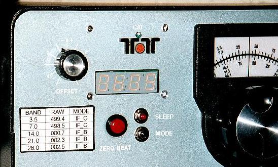
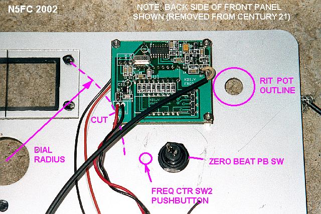
The unit readily measured the 5 - 5.5 MHz VFO signal on the C21, so we found a spot to mount it on the front panel, left of the main analog dial, right of the RIT control, and just behind and slightly south of the logo. Of course, this meant that we had to cut a rectangular hole in our pristine C21, and that took about 50 milliseconds of internal deliberation before we decided to do it. Steve supplies good documentation, which happens to include a full-size drilling template, and we used that to mark the hole, then cut it out with a nibbler and filed it clean. Then we drilled 3 holes to mount the freq counter. In order to avoid mechanically interfering with the rotating analog dial, we trimmed a 1/4 x 3/4" triangle off the corner of the board, as you can see below:
(click on the image above for a larger, annotated version)
We took 12 VDC power from the nearby lamp socket, and mounted two small Radio Shack pushbuttons (p/n 275-1571) just to the right of the ZERO BEAT pushbutton. Later, I discovered I didn't really need SW1, since there isn't a compelling need to turn the display off in a receiver that draws 3/4 of an amp HI HI. We tapped into the VFO output at the feedthru terminal on the rear/side of the PTO, via the 2.2 pF capacitor (supplied by KD1JV), and used some RG-174 mini coax to route the signal to the freq counter board.
Here's what the installation looks like from the front:
(click on the image above for a larger version)
The C21's mixing scheme leaves much to be desired, but the KD1JV freq counter is up to the task. Because the C21 uses un-trimmed crystals for each band, band-to-band variations can be as much as 3 KHz. Even if you calibrate the analog dial for "zero" error on one band, it was bound to be off on the others. All the more reason to use a digital dial, but the dial must be able to accommodate the band-to-band offsets. After calibrating the frequency counter to CHU Canada on 7335 KHz, I made a table of offsets for each band. To do this, I first tuned the RIT to "zero"; that is, when I press the ZERO BEAT pushbutton (on the C21 front panel), there was no change in the frequency reading on the digital dial. Then, I transmitted into a dummy load, measuring the frequency with an external frequency counter (I used an OPTO 8000), and adjusting the VFO to the bottom of the band, i.e., 7.000000 KHz for 40 Meters, 14.000000 KHz for 20 Meters, etc. With the external frequency counter at the "zero" band edge, I noted the reading on the new digital dial. For example, with the TX frequency at 7.000000 KHz, the digital dial's raw reading was 498.5. I did this for each of the five bands, keeping a table of the "RAW" values. Later, I taped the table to the C21's front panel, for ready access when changing bands. (See the image above)
The KD1JV freq counter has several modes, which can apply an offset to the measured frequency in order to correct the digital dial. The freq counter is unique among other designs I have seen, in that it actually samples the frequency of the IF offset, remembers it, and applies that to the measured frequency. This is perfect for the Century 21, if you've made a table as I described above.
The following procedure needs to be applied each time you power-up the C21 or change bands:
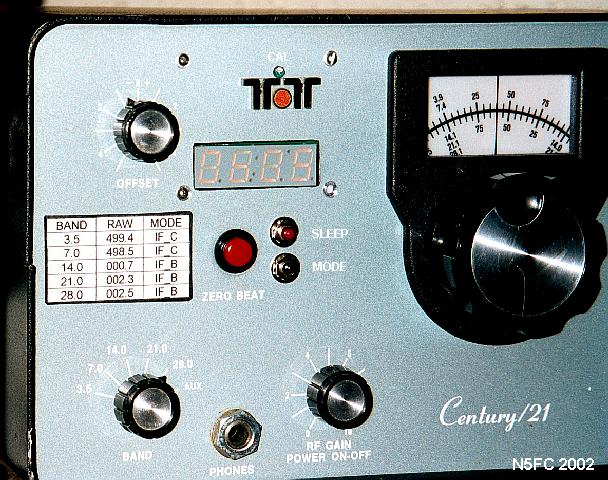
Here's an overall view of the C21 front panel, at the operating position:

(click on the image above for a larger version)
That's it! You're calibrated! Wow, is it nice to finally know exactly where the QRP calling frequencies are ;-)
73, monty N5ESE