N5ESE's Version of the K5JHF Morse Code Device

(click on any picture to see larger version)
...more pix below...
(click on any picture to see larger version)
...more pix below...
| NOTE: 'N5FC' is my former call. This project was constructed while that call was valid, and you may observe references to it. |
| NOTICE!! John Fisher, K5JHF, now has a new version of the MCD out, which is even more compact and has all the features of the old version, plus a unique sending-practice mode. See K5BCQ's web page for kit info, or contact John via e-mail for more information. |
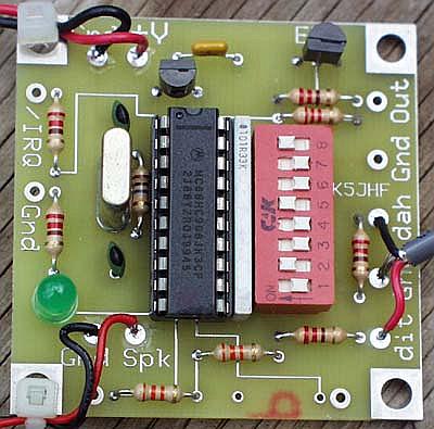
The Morse Code Device (MCD) described here was created by my friend John Fisher, K5JHF. The core unit is built on a 2 x 2 inch printed circuit board. Powered by a Motorola (now made by NXP) MC 68HC908 microcontroller, programmed to provide many interesting and useful functions, to support learning and operating "CW" (morse Code).
This is an amazing little device. Connected as shown here, it provides all the following functionality:
The MCD's morse tutor can be switch-selected to provide random character or word practice at any speed from 1 through 32 wpm (words-per-minute), or it will provide incremental practice sessions based on the "Koch" method for learning and/or increasing morse receiving skills. For sending practice, use either a straight-key or paddle to key the built-in code-practice-oscillator (CPO). When you've finally got your ham ticket, use the iambic-keyer mode with your own favorite set of paddles to key your transmitter. Or, if you're using the mic or a straight key, use the 10-minute ID mode to remind you to send your call per FCC rules.
While the MCD is probably most appropriate for those just beginning with CW, or those wanting to practice up before going on-the-air, there are a couple of functions that are excellent for even the experienced CW-er. My favorite is the random-word mode, which sends short words at the pre-selected speed. This can be really helpful for developing "copy-by-ear" capability, especially at speeds too great to copy by hand.
Mode selection is via an 8-position DIP switch. The first three switch positions determine which of 8 different operating modes the MCD will operate. The remaining 5 determine the speed of the MCD, or the Koch pattern subset, which can vary from 2 characters to 43 characters (sent at 5 or 10 wpm), depending on the switch positions. Very clever! And very compact.
I packaged mine in a Radio Shack project box (RS 270-211). A little larger than a pack of cigarettes, this case was intended to provide a package for an IR transmitter. It houses a 9-Volt battery (with a sliding cover), and has just enough room to mount the MCD, a small speaker, a power switch, and all the I/O connectors.
To help those who wish to duplicate my packaging, I've provided a 1:1 scale drilling template (in MS Word 97 format) for the printed circuit board and speaker holes for a 1-3/8 inch diameter speaker.
I used the templates above to locate holes on the top and bottom covers of the project case. Before installing, I lay the crystal down flat against the board, so that it wouldn't interfere in mounting. Also, I replaced the original LED with a high-efficiency type (RS 276-310), and mounted it on the opposite side of the board (the solder side), leaving enough extra lead length that it could protrude slightly through the case when installed. To mount the pcb, I used 4 each 1/2- inch spacers. The 1/2-inch spacers are just a sweegey too high, and you might want to file them down about 1/32 - 1/16 inch. Once mounted on one half of the case (as close to the 9V battery compartment as possible), I cut a rectangular hole in the other half of the case, 0.45 x 0.85 inches, for accessing the DIP switch (for mode selection). If done correctly, there will be plenty of room for switches and i/o jacks on the cases's end panel, and the DIP switch will be accessable from the "bottom" (the side with the battery sliding-cover).
I mounted the mini-speaker (I used a 1-3/8 " junker, but you could use the 29 mm speaker RS 273-092), using 5-minute epoxy. It mounts over the speaker holes, and under the MCD's pcb, approximately centered under the MCD.
Four components mount to the project case's end panel: the 1/8" stereo headphone jack (RS 274-246, a closed-circuit type), a SPDT mini-toggle switch (RS 275-624, for on/off ), a 1/8" 3-conductor jack (RS 274-249, for the paddles or straight key), and a 1/8" 2-conductor jack (RS 274-251, for the keyer output) . Here's the wiring diagram:
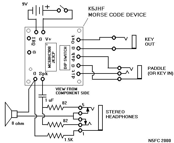
In addition to the wiring shown, I made the following modifications to the MCD pcb, which significantly lowered current consumption, and improved RFI susceptability:
After mods, power consumption was observed to be:
The pictures below are offered as visual aids to those building and packaging the MCD as I did:
Top View Overall [~115 KB]
Bottom View & DIP Switch [~119 KB]
Construction details, cover removed [~150 KB]
Wiring details, cover removed [~158 KB]
![Top View Overall [~115 KB]](k5jhf_mine_top.jpg)
![Bottom View & DIP Switch [~119 KB]](k5jhf_mine_bottom.jpg)
![Construction details, cover removed [~150 KB]](k5jhf_mine_inside.jpg)
![Wiring details, cover removed [~158 KB]](k5jhf_mine_detail.jpg)