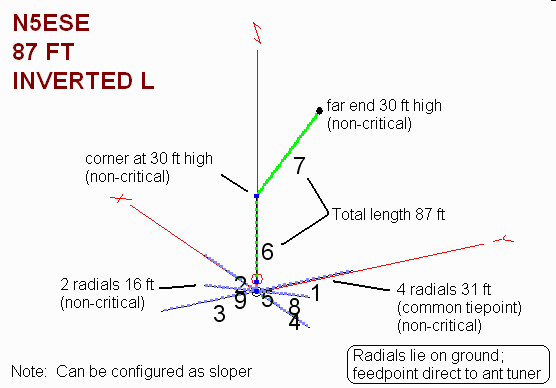
N5ESE's 87 ft Inverted "L" Portable Antenna


| Antenna Disclaimer |
|
Right from the top of this page, I'm going to say that I'm an antenna experimenter, not an antenna expert. Purely seat-of-the-pants. In fact, you might even say I'm an antenna cynic. I know how to use antenna analysis tools, and I often do, but I take them with a serious grain of salt. I've found, in my 35 years of experimenting, that some antennas work much better than predicted, and some work much worse (and that they're more likely to work worse than better HI HI ). Still, I find experimenting to be one of those true joys of amateur radio, and I encourage all of you to just "try it out" for yourself, and for Pete's sake, don't take my word for it (nor my explanations).
I find that most technical people do the following (and I am no exception): upon observing a phenomenon, we make up an explanation for why we got our observed results. We base this explanation on the current subset of knowledge that we've gained from education and experimentation and folklore, and we're not likely to look for another explanation until we have another experience which forces us to expand or revise our previous explanation. Please realize this is the case with me, also, and then enjoy the web page. |
Here's one of my favorite antennas for QRP portable operation. It provides easy setup in the field, is extremely compact, and provides excellent performance on all bands 80 thru 15 Meters. It's a non-resonant antenna, but don't think for a minute that you lose anything from that. Using a field-radial system as shown, the feedpoint impedances tune readily on all bands 40-15M on my Elecraft K1's built-in automatic antenna tuner, and I've used it with great success with my Norcal BLT Z-match. Gain on all bands is very respectable, except on 30 Meters, where it is nevertheless quite usable. You may want to use a 1:4 impedance transfiormer (toroidal balun) to improve your chances of matching on 20 & 30 Meters, when using the BLT tuner.
Here are the EZNEC-calculated feedpoint impedances for each CW QRP Calling Frequency:
80 Meters (3055 KHz) : Z= 69 +j308 ohms
40 Meters (7040 KHz) : Z= 111 - j232 ohms
30 Meters (10110 KHz) : Z= 1693 + j1466 ohms
20 Meters (14060 KHz) : Z= 239 + j450 ohms
15 Meters (21060 KHz) : Z= 1700 + j591 ohms
I built mine of 87 ft of AWG 22 teflon-coated wire. For a counterpoise, I use four 31 ft radials, formed like an "X", with two additional 16 ft radials to cover 20 Meters. The radials are AWG 24 wire, also teflon insulated, and connect to a common tie-point, with a 30 inch tail for connecting to the antenna tuner or rig. I prefer the teflon-insulated wire for field antennas, as it tends to be less susceptable to changes due to moisture. While one could use a single counterpoise wire, I believe the extra wire radials help to establish a more consistent and stable "ground" system in the field, and thus more predictable performance from the antenna. Both the antenna and the radial system fit into a sandwich-sized ziplock bag.
This antenna is very flexible in its deployment. You'll get similiar performance whether it's deployed as an inverted "L" or a "Sloper". It will work best with the far end up about 30 ft or more, but it will give excellent performance even if only raised 15-20 ft. In the inverted "L" configuration, try to get the vertical portion up at least 15 ft if possible. Lower antennas will tend to radiate more energy upward on the lower bands, but this is not at all a disadvantage for domestic contacts.
Here are EZNEC patterns and gains for the illustrated Inverted "L" configuration:
80 Meter Pattern
40 Meter Pattern
30 Meter Pattern
20 Meter Pattern
15 Meter Pattern
For those who want to model this themselves, the text-readable .EZ file can be downloaded -here-
73,
Monty N5ESE
dit dididit dit