(click on picture above to see larger version)
A cheap chinese PLJ-8LED Freq Counter Module, at less than $20, is an amazing technological bargain.
To have a frequency counter for HF at this price is unheard of, but to have it cover VHF and UHF as
well, is nothing short of "gotta have it!" As of 2023, there are several versions of this,
some having claims of frequency measurement to 2.4 GHz. Yeah, maybe... we'll talk about that later
The version I bought in 2020 claimed 1 GHz operation, but even that has some caveats.
All versions I've seen are based on a PIC uC, and are clocked with a good quality +/-2.5ppm clock
oscillator. The PIC microControllers have fairly definitive timing and latency on their internal
timers and timer interupts, so they are uniquely positioned to do a passable job on frequency
measurement - though probably not as good as a hardware-based timebase and gating circuit and
front-end. Still, for the price, it offers a very usable counter at a hundredth of the price of a
lab-grade instrument. And should suffice for all but the most demanding ham radio applications.
Our approach to packaging and using this will be:
   - Our implementation will be straight Frequency Counting (No IF Offset functions)
   - One front panel pushbutton allows us to select gate time (0.01, 0.1, 1 Second)
   - Both original (module-mounted) pushbuttons are still available via access holes in front panel
   - Front-Panel Toggle switch for Hi-Z or 50-Ohm termination (50-Ohms usually needed for VHF/UHF)
   - AC-line power only (115VAC) - internal regulated power supply

(click on picture above to see larger version)
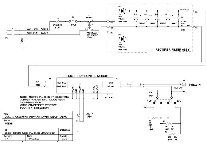
The schematic is pretty simple. The PLJ-8LED module only has two connectors. One is for input
power (8-14VDC), and one is for the input signal.
We fuse and switch the incoming AC line voltage, and feed a small 2.5VA 12.6VCT filament transformer,
which in turn is full-wave rectified and filtered. This will provide unregulated +8VDC (nominal)
to the PLJ-8LED module. The PLJ-8LED has onboard regulators to develop the voltages needed by its
circuitry.
On the signal input side of the PLJ-8LED, we use coax to route the signal. A switch is provided to
add-in a 50-Ohm termination if we want it. Generally, we will want to use that termination for
VHFand UHF, but not necessarily for HF signals. The 50-ohm termination will help preserve the
input signal's waveform, and is particularly needed if we mount a short BNC antenna at the input
(as when measuring the output frequency of a handheld VHF/UHF transceiver), or if we are using an
inline attenuator from the signal source.
We also tap off the "DELTA" pushbutton (onboard the PLJ-8LED) and route to a front-panel pushbutton,
so that we can change/select the gate-time (0.01 Sec, 0.1 Sec, 1 Sec) as needed for faster readings
or better resolution.
We wanted a nice-looking yet compact enclosure that would provide adequate shielding for the noise-
sensitive electronics in the PLJ-8LED front end. We decided on the 6.1"L x 3.3"W x 2"H+
Hammond 1590P1BK, a diecast aluminum box with a black powder-coat finish.
We use a small high-quality perf board (with plated-through holes on 0.1" pitch) to mount the
rectifier/filter components. See the pix below:
(click on either picture above to see larger version)
Below are more pictures of the internal construction (nice and roomy, for a change...):
(click on picture above to see larger version)
(click on picture above to see larger version)
(click on picture above to see larger version)
Testing the PLJ-8LED-H  8-Digit Frequency Counter Module - 20201207/mdn
   - Current Consumption (while Counting): 155 mA @ 8 VDC
   - Input Voltage (RF) for Stable Readings:
	- 30 mV-rms @ 32 MHz
        - 30 mV-rms @ 95 MHz
	- 200 mV-rms @ 170 MHz
   - Temperature:  Hot spot is the 7805 Regulator (TO-220, onboard the PLJ-8LED module)
        After 30 minutes, Case Temp is 160 Def F (Ta = 72 Deg F)
        represents a Delta T of 49 Deg C
        Note: Recommend running at 8-10V, but not more than 12VDC
   Note 1:  Subject to stray noise, including radiated noise - needs
            an RF-tight box & good power decoupling
   Note 2:  IF Offset Operation not checked
   Note 3:  Oscillator Trimmed to 10.000.000 using GPS Disciplined Osc.
Using a cheapo BNC-mounted telescopic antenna (non-resonant), I was also able to get good frequency
measurements on my handheld VHF/UHF (2M/70CM) transceiver.
Andrew, ZL2PD provides a user manual which includes some schematic snippets. You can find that - here -.
ZL2PD has graphs (in dBm) for sensitivity. His measured sensitivity on the HF spectrum was in the
ballpark with my observations. But on the VHF/UHF bands his measurements showed considerably
(+20dB) better sensitivity than what I observed. That may reflect changes in the front end circuitry
between the version I had (chinese version 'H' circa 2020) and whatever version he was testing.
Be careful about possibly overloading the input. There appears to be some front-end protection
(some very small back-to-back diodes), intended for very short-term surges, and not for sustained
overloads. When using an antenna, for example, as the sensing element, I can imagine that a
transmitter too close by could smoke the front end. Always keep the peak-peak value at less
than 5V (measure first, if you're not sure). 5V pk-pk is about 60mW (+17 dBm) into a 50-ohm load.
If you're transmitting more power than that (and you probably are) be very careful about
proximity of the receive antenna to the transmit antenna.
Concluding, for what probably amounts to less than $100 investment (packaging, power supply, et al),
I have a compact and reasonably accurate freq meter which I find myself using more often than my
old HP-5300 workhorse.
73,
Monty N5ESE
dit dididit dit