(click on imageto see larger version)
This circuit was intended to replace 4A thermal/magnetic circuit breakers for the battery-supplied
lighting circuit in my new workshed. The old circuit breakers seem to fail (making lights cycle
at the most inconventient times) after about 1 or 2 years.
It is designed around the Analog Devices LTC4368 "e-fuse" chip.
This is a very versatile chip, capable of UV/OV (undervoltage and overvoltage) protection, as well
as reverse-polarity protection. It will work with input supplies from +2.5 to +60V DC, and you can
even configure it to act as an e-fuse in a negative supply. As a minimum, it needs a few resistors,
including a "current sense" resistor sized to provide a 50mV drop as your set-point for "fuse
current". And it also needs at least one external power MOSFET resistor.
TIP: Often, e-fuse chips are disguised as "Hot-Swap Controllers" - look for these is you are searching
for more available or cheaper devices than the one I chose, but be sure to note the Input Voltage range.
Texas Instruments (TI) has a nice appnote on e-fuses, which shows some discrete-element circuits,
and that can be useful in understanding the ins-and-outs of e-fuses. Catch that - here -.
One of the nice things about e-fuses is that there is no need to change a fuse. Plus, you can
decide whther you want an "automatic reset" (after a delay) or "latch off" until a manual reset or
source-removal occurs.
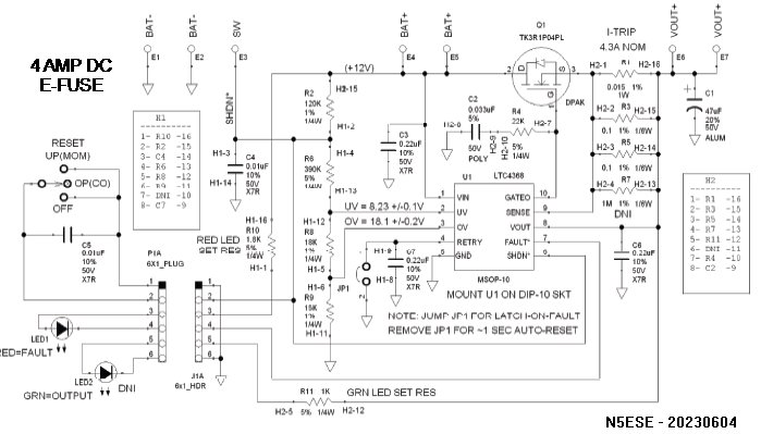
Here's achematic of what I did for my 4-Amp e-fuse:

(click on imageto see larger version)
This is more complicated than it needs to be, because (of course) I'm inclined to use all the
features of a chip, even if I don't need them - HIHI. For a straight-ahead reseetable fuse, you
could pare this down to 2 resistors in the input voltage divider, the current sense resistor, a
pass transistor, and a timing capacitor for the reset delay - and (of course) the chip itself. Oh
- and one or two decoupling capacitors, as needed.
In my version, this is a 4A electronic fast-acting fuse. Jumper JP1 provides:
- JUMPER IN - circuit is "latching" upon fault
(must be manually reset via outboard momentary switch toggle
- JUMPER OUT - automatically resets about 1 sec after fault
The trip point is set by parallel resistors R1 || R3 || R5 || R7 to the value of
A=0.05V/R re 0.05 / 0.0115 = 4.33 Amps
By selecting new resistors, the fuse could be set as high as 12.5A
The circuit also monitors input voltage and will "fault" if the input
exceeds 18V or falls below 8.5V. The undervoltage value is probably a little low
for a lead-acid battery - 10.5 or 11.0 Volts would probably make more sense.
An external Red LED indicates a fault has occured.
An external Green LED (if installed) indicates output voltage is present.
A SPDT-CO Toggle switch (ON-OFF-MOM) acts as the Circuit Breaker control:
- Center-Off - normal operating position
- DOWN - Forces the circuit OFF (i.e., shutdown)
- UP (MOMENTARY) - provides circuit reset after overcurrent or other fault
Voltage drop (VIN to Vout) using the designated pass transistor should beless than
0.075V (at 4A), and less than 0.12V at 12.5A.
The LTC4368 is rather pricey ($6 or so), and if you can live with a fixed-voltage scheme (5V or 12V),
then the STM STEF series can cut the price by half or more. Unfortunately, the surface mount
package on these devices make them rather challenging to work with (for the average homebrewer).
In fact, in my investigations, I found most of the e-fuse ICs that are actually "obtainium" have tiny,
challenging surface-mount packages with heat-sink pads underneath. So those were not selected.
There is an excellent paper by Rod Elliott on various approaches to e-fuses, and it is worth a study,
as it reveals the pitfalls of the cheaper or simpler circuits you might be tempted to try. This
is not to say a simpler or discrete approach might not be possible, or even might not be right
for a particular application. But give a look -here -.
I looked at doing this with discrete elements, and couldn't come up with a cheaper method than this
that had reasonable set-points over temperature and applied voltage. I also looked at doing this
using discrete IC's (current sensors + comparators + reference) that would be more stable, and it
still came out more expensive and using more real estate than the solution presented.
73,
Monty N5ESE
dit dididit dit