N5ESE's QRP Dummy Load With Built-in RF Detector
(click on any picture to see larger version)
(click on any picture to see larger version)
| NOTE: 'N5FC' is my former call. This project was constructed while that call was valid, and you may observe references to it. |
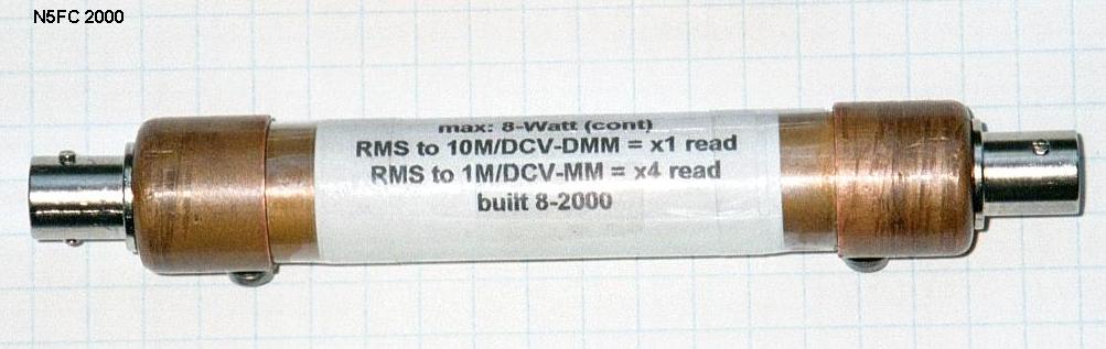
This is yet another variation on the "parallel resistor" dummy load. [Go -here- for a discussion on dummy load theory]. This is another one I built during my infatuation with copper pipe. It's suitable for QRP HF operation of 5-watts or less average power, and should be adequate for continuous operation at that level. It's light and compact, about 5-inches in length overall. This one is unique in that it has a built-in RF detector, with scaling, that may be used with your DC Voltmeter to measure power.
The 1/2" copper pipe provides a convenient, compact form factor, is an excellent shield, and helps to dissipate heat to the outside world. Copper end-caps, available at most any hardware or plumbing supplier, provide a means of mounting the two UG-1094 BNC jacks and closing the unit.
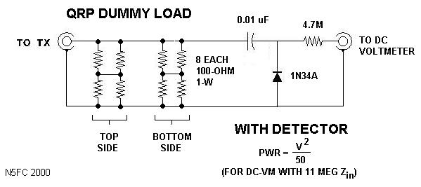
This version uses 8 each 100-ohm 1-watt 5% metal-oxide resistors, available from Radio Shack for a mere 25-cents each (RS 271-152). All the detector parts (yes, all three of them, a 0.01 capacitor, a 4.7-Meg resistor, and a 1N34A diode) are also available at Radio Shack. You would be hard-pressed to spend much more than $5-6 dollars on this project. The resistors are good through the HF range, but don't do particularly well at VHF. Here's a schematic:
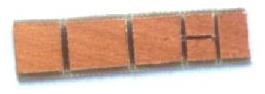
We'll fabricate a printed-circuit board from scrap double-sided copper board, cut to 1/2 x 2-inches, and grooved to form pads on each side, as shown in the layout below. On the top side, we'll mount 4 of the 8 resistors, and on the bottom side we mount the remainder. Simply tack-solder the resistors to the board. Where required to connect the resistors, we drill a small hole through the board, and solder a wire in place top-to-bottom. On the top side, we end up with a 100-ohm, 4-watt equivalent resistor (a pair of parallel 100 ohm resistors makes 50 ohms, and two pairs in series make 100-ohms). When we join the top and bottom in parallel, our equivalent resistance is 50-ohms (two 100-ohm quads in parallel).
Mount a UG-1094 BNC Jack in each of the two copper end-caps. then, connect the pc board assembly directly to the center post of the BNC connector, soldering same. Make all other interconnections with teflon-insulated wire. DON'T SUBSTITUTE OTHER INSULATIONS! Sorry, I know teflon wire is tough to find, but other insulation types will almost certainly fail when the resistors get hot. Wrap the entire pc-board assembly in teflon tape (often called plumber's tape, available at any hardware store. DO NOT use other types of tape (they will melt!). Next, we slide a short piece of 1/2-inch copper tubing over the assembly, slipping it into the BNC/end-cap. At this point, an ohmmeter should verify 50-ohms. Finally, solder the detector output wires to the second BNC, and mount the other end-cap to close and shield the unit. Drill and tap a screw into both end caps to connect the shield both electrically and mechanically.
When supplied RF power for an extended time, this dummy load can get quite warm, even with just 5 watts. Be aware, and plan for it. (Read the "WARNING!" above). My version has an SWR of 1:1 throughout the HF range (DC to 30 MHz). Measuring power is easy, and accurate if the detector's resistor is sized to work with your DC Voltmeter's input impedance. Read the DC Voltage, square it, and divide by 50. Example: we read 10 Volts, which is 10 * 10 / 50 = 2 watts.
For a more complete discussion on the detector and it's accuracy, and sizing the resistor for your voltmeter, see our page on RF probes.
73,
monty N5ESE