N5ESE's External DDS-VFO for Vintage Rigs (Using the WA1FFL DDS) (2020)
(used with my Heathkit HW-16)
(click on any picture to see larger version)
(click on any picture to see larger version)
For years I used the venerable (and fully compatible) Heathkit HG-10B as an external VFO for my Heathkit HW-16 RX/TX.
Jim Hagerty, WA1FFL offered a DDS Kit based on the superb 14-bit AD9951 with excellent specs, great reviews,
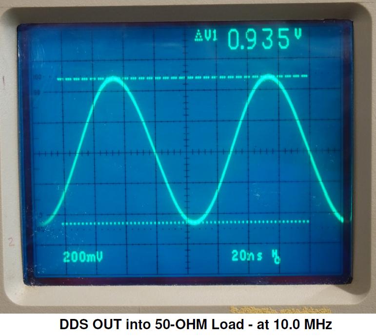
Just having a good, clean, RF worthy DDS signal is HUGE, but a half volt peak-to-peak sinusoidal RF into 50-Ohms isn't going
Jim WA1FFL offered an aplifier kit work with his DDS, and I figured not to reinvent the wheel, so I built his kit. The amp was
The effect of the Amp is striking. Below, we see what we started with (the DDS itself into a 50-Ohm load):
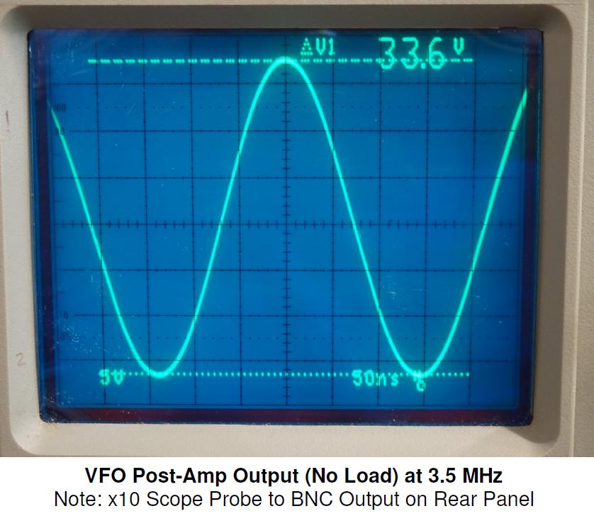
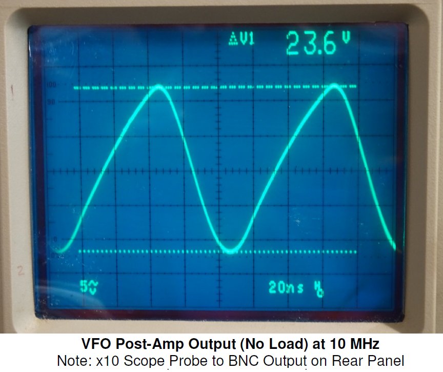
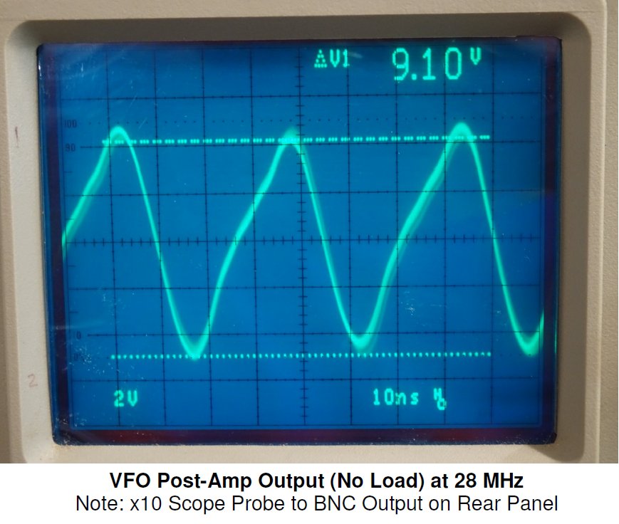
And the 3 waveforms below show what we have out of the amplifier (in this case, at 3.5 MHz,10 MHz, & 28 MHz, at No-Load):
There is some "glue" needed to put the DDS functionality together with the outside world. The WA1FFL DDS Board
Also, the WA1FFL DDS can be keyed with a 5V Logic signal, but keylines to an external rig may involve +12V logic (on
Further, timing can be an issue keying-wise, if there are indeterminate delays in the transmitter for passing a keyed VFO
All these issues add complexity to the project. My solution was to design a dedicated board just for power and keying control.
There are two distinct circuits on this board, having in common only ground and +12VDC Power:
1. Power - This can be either +12VDC from an external power adapter (preferably linear) or
we convert external
The new Power & Keying Control Board is built on perf stock, and can be seen below (top & bottom):
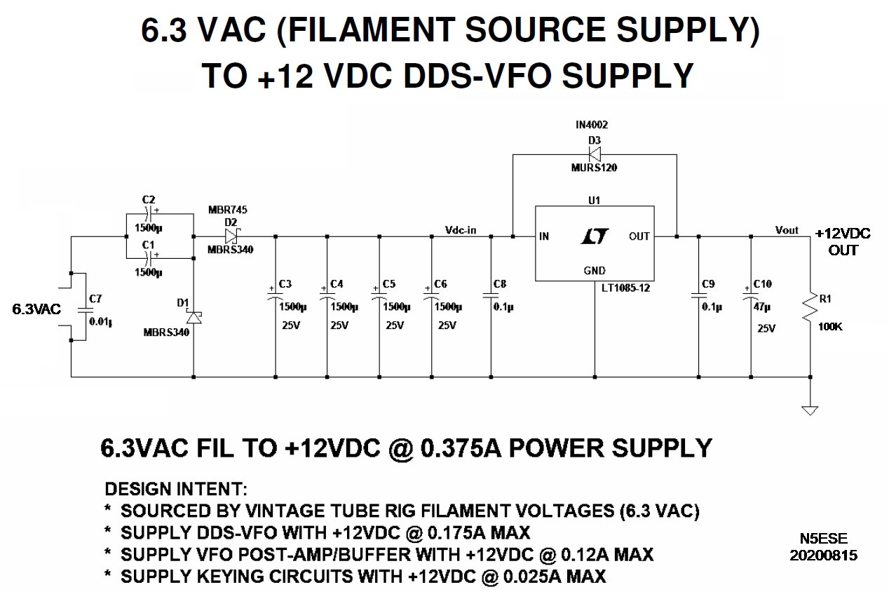
Below is a schematic of the Power Circuit (half of the Power & Keying Control Board):
The power circuitry accepts 6.3VAC via the vintage rig's AUX connector/cable, rectifies it in a classic voltage doubler, filters it,
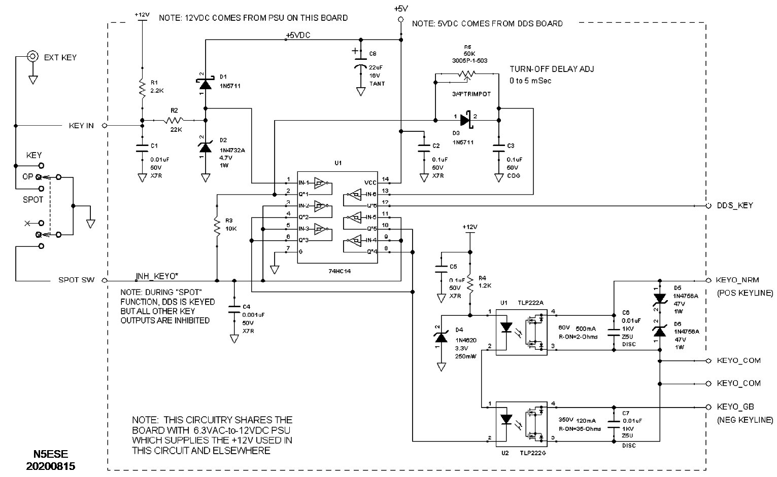
Below is a schematic of the Keyer Control Circuit (other half of the Power & Keying Control Board):
The Keyer circuit does several things. On the far left, the operator key (or keyer output) is applied to EXT KEY (on the rear panel)
The chassis wiring for the cabinet I chose is a 3-page document, and way too detailed for this overview.
We chose a reasonably compact 2-piece aluminum enclosure with a sloping front panel. Alas, I can find no datasheet or part number on
The enclosure is a tight fit - what my buddy Homer used to call a "free-running press fit". Below, you can see all the controls, LCD,
Below is the DDS Board Stack, consisting of the WA1FFL DDS (bottom, upside down), a shield/mounting plate (middle), and the
Since I put this VFO in service in fall of 2020, it has done an exceptional job with the HW-16: rock-stable signals, superb keying,
Here's a picture of the DDS-VFO and my HW-16, as it sits at my operating position.
It worked well for its vintage (1960s-1970s), but it wasn't up to the job on 15 Meters (a tad chirpy) and it
certainly didn't have the stability we've come to expect in the 21st century. So I was eager to have the additional performance
of a modern DDS, and also the flexibility to utilize it with other vintage crystal-bound rigs like my Hallicrafters HT-40.
My Pick: the WA1FFL DDS
and the features one needs to make it usable with a homebrew or vintage rig (re keying capabilty, programmable offsets
for IFs, and enough user-memory to program for different bands or rigs). Jim provides a Power-Point
of his presentation at the Boxboro Convention in 2012, and if you'd like to investigate the DDS design, download that PPT -here-.
I bit the bullet and coughed up the $150 for this kit, because I was confident it would serve my purpose. You can probably
get cheaper DDS's, even kits, but you won't approach the RF quality of this one with the 14-bit A/D.
Here's a couple of pictures of my build of his board:
(click on any picture to see larger version)
On To The Rest
to hack it for a vintage tube transmitter or receiver. Besides, you need some knobs and switches in order to make it play - oh, and a power
supply up to the task of sourcing clean DC to a 14-bit analog device. All told, this makes for a more-than-a-weekend long project.
A VFO Buffer Amplifier
featured in CQ Magazine in June,2011, and Jim provides this link to the article.
After building, I found it "worked as advertised". See pix below:
(click on any picture to see larger version)
When applied in a real-world circuit (i.e., a tube's grid circuit), expect about 25% less peak-to-peak applied voltage
Note that the distortions in the 10 & 28 MHz waveform are most likely caused by my X10 probe ground leads.
Power Supply and Keying Circuitry
is powered from +5VDC, while the typical ham radio world is powered at +12VDC. Besides, the WA1FFL Amp needs minimum
+12V to
do its job. And to interface with vintage tube gear, it would also be very nice to rob power from the rig itself
(most vintage
rigs have an auxiliary connector), and that generally means 6.3 or 12.6 VAC.
a modern rig), or possibly negative keying (grid-block keying on the HW-16), or higher voltage higher current positive
cathode keying (as with the HT-40 and many other vintage tube rigs).
signal. Usually, the external VFO is expected to be running and stable before the transmitter itself is keyed, and stay that way
until after the keyed circuits turn off. So we need a means of handling that.
6.3VAC to regulated +12VDC for use internally (the VFO Amp board needs +12V)
2. Keying - Accept Key inputs from Front Panel or external Key or Keyer, and generate optically isolated
Keying Outputs with appropriate timing.
Additionally, we provide a user front panel switch "SPOT" function, which inhibits keying, but
allows the VFO to run unkeyed, so it can be heard in the local receiver.
Note: Clicking on the first image will bring up an annotated picture in a new tab, whereby you
can see the signals we described earlier. In that image, the upper half (of the board) is occupied by the
circuitry that converts 6.3VAC to regulated +12VDC. The bottom half is the Keying & Control Circuitry.
(click on any picture to see larger version)
(click on any picture to see larger version)
and finally regulates it to +12V using a 3-terminal regulator. Alternatively, the user can simply supply (at the rear panel)
+12VDC from an independent low-noise low ripple linear power supply.
(click on any picture to see larger version)
and becomes the "KEYIN" signal. It is NOT simultaneously applied to the external transmitter. Note the front panel DPST-NO
switch depicted on the far left. To operate (key) normally, it is left in the center-off position. To "TUNE" it is up, and
provides a continuous key-down condition to the transmitter. Switched down to "SPOT" position, it provides a means of keying the DDS
continuously yet inhibit keying to the external transmitter. Input keyline KEYIN is positive-keying (like almost all modern
rigs) and is surge and RFI protected. U1 (hex inverter) buffers KEYIN and INHKEYO and also drives the delay circuit and the two
optocouplers. R6 (trimpot) and C3 provide a turn-off delay so that the DDS-VFO is kept keyed long enough that the transmitter can
unkey in their oftentimes slow fashion. A typical delay setting would be 2 milliseconds, but it can be tweaked from 0-5mS. The
KEYO_NRM optocoupler is a positive keying output to go to modern +12V positive keylines or vintage cathode keylines. That
optocoupler exhibits about 2-Ohms key-down, can handle 40V max key-up (check your transmitter keyline), and can sink up to 250 mA max.
The positive optocoupler is further protected from narrow (sub-mS) surges that might enter via the transmitter keyline. The
VKEYO_GB optocoupler provides a grid-block keyline good to about 300V. Key-down on the grid-block keyline is about 35-Ohms, which
should work fine for most vintage rigs. Both those keyline outputs are provided at the rear panel, and only one is used in any
given setup. Note that the logic-level circuits on this board are powered by +5VDC robbed from the WA1FFL DDS board.
Packaging the Whole Shebang
But, if you're so inclined, you can download that as a PDF - here -
it. I am recollecting it is a LMB # UNC-4-5-5 (4"H x 5"W x 5"D) purchased from Allied Electronics, but I can find no record of it.
The LMB UNC series data can be found - here - but mine is not listed as a standard size.
Sorry about that.
switches, and connectors mounted in the cabinet (along with wiring, but sans the DDS and VFO Amp); The front panel is left, the
vented top mounts the Power & Keying Control Board, and the rear panel is on the right. The DDS board stack (WA1FFL DDS plus VFO Amp)
will end up taking most of the middle space, and it's going to be a squeaky fit.
(click on any picture to see larger version)
WA1FFL Amp (top, facing up). This assembly needs to be carefully located to the bottom sheet metal "chassis" (enclosure) so as not
to interfere with the abundance of wiring and switches and connectors ahead and behind it. In point of fact, I have a note attached to
the side of the unit reminding me that I need to be crazy careful assembling and disassembling so as not to pinch, snag or break wires.
(click on any picture to see larger version)
Conclusion
and even on 15 meters, full power with no hint of chirp. Front panel controls all work as planned. Plus, I have the flexibility
to drive the old HT-40 or any homebrew tube project I might devise. And I know exactly what my frequency is.
(I just have to remember to "spot" it after tuning around with the receiver HIHI)
(click on any picture to see larger version)