IN3 DC-RX
(One-Cubic-Inch Direct-Conversion Receiver)by Monty Northrup, N5ESE

| NOTE: 'N5FC' is my former call. This project was constructed while that call was valid, and you may observe references to it. |
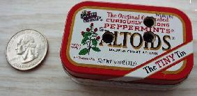
When my wife Carolyn showed up after an afternoon's shopping, sporting an Altoids "Tiny Box" (of mints), she was surprised at how I carried on about it. Upon seeing the 2-1/4 x 1-3/8 x 1/2" box (1.5 in3), I immediately began considering what I might build inside it. There have been numerous projects described for sardine cans and regular-sized Altoids boxes, but this box was a quarter the size of those. The project described herein is the end result of a month-long project to stuff something useful inside the teensy box.
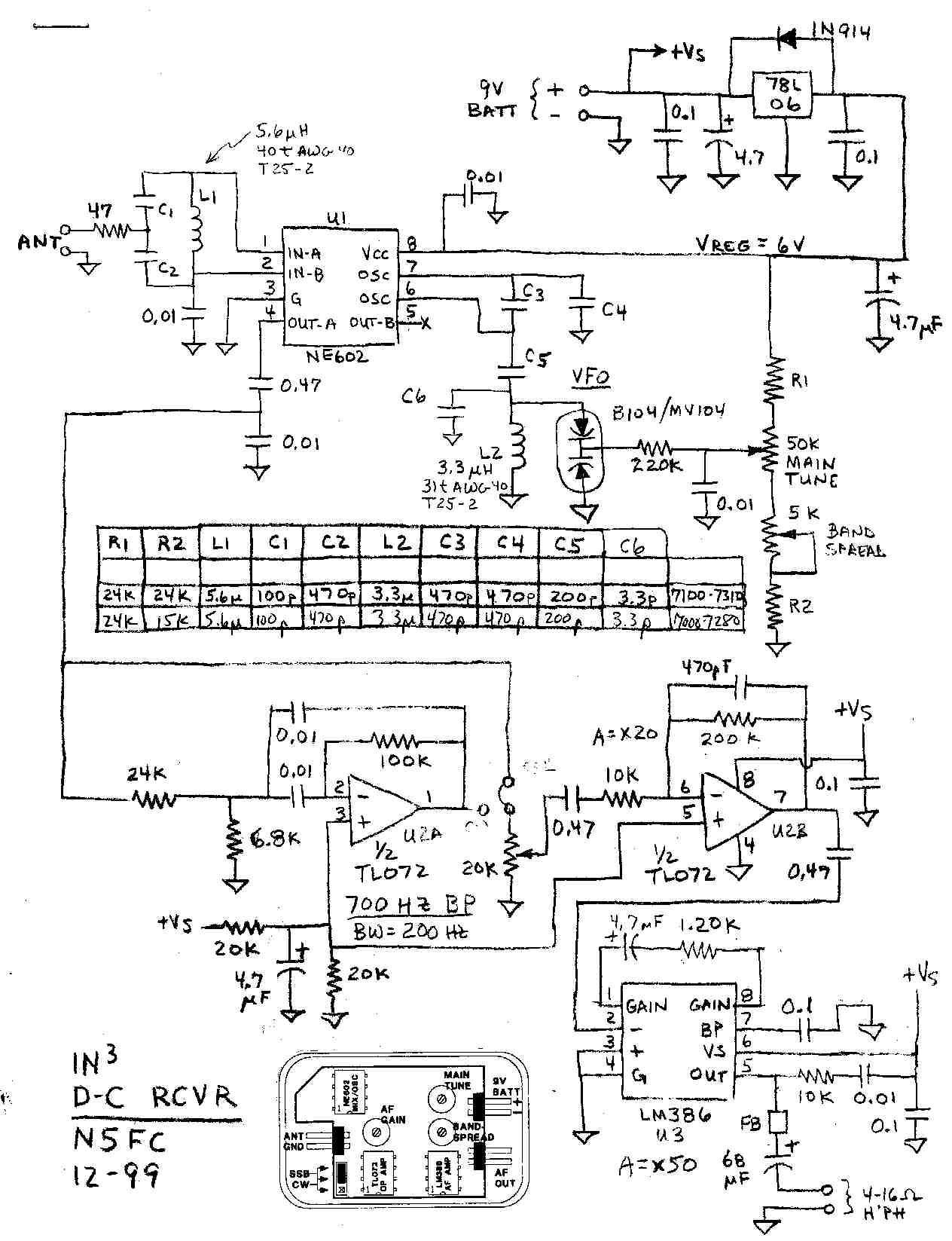
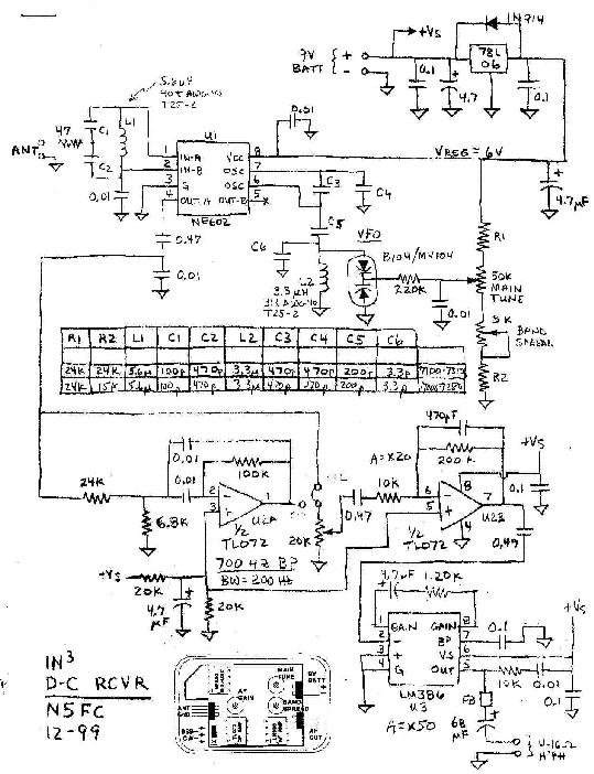
It was decided to attempt a varactor-tuned, 40 Meter direct-conversion receiver. Rather than skimp on circuitry, we wanted plenty of audio gain, good sensitivity, stable VFO tuning, and a choice of CW or SSB audio filters. Not too surprisingly, in order to get all this into the tiny package, we would rely heavily on surface-mount resistors and capacitors. See the schematic here: (MS Word 97) / large JPEG Image / medium JPEG Image..
We decided on the venerable NE602 as our Direct Conversion engine. This chip provides about 15 db conversion gain while doing a pretty decent job of mixing the RF signal down to audio baseband. To provide some front end selectivity and matching, yet avoid tuning capacitors (a luxury in size we couldn't afford), we built the input tank from fixed components, and adjusted the input inductor by squeezing and spreading turns. Since the circuit is fairly low-Q at this point, we could get away with this.
In addition, we utilized the NE602's internal oscillator in a varactor-tuned Colpitts VFO circuit. We've had experience with this before, and have found the NE602 oscillator to be remarkably resilient, forgiving, and stable. Naturally, to enhance VFO stability, we used NPO/COG ceramic capacitors throughout the tank circuit. Also, we regulated the supply voltage to both the tuning-resistor chain and the NE602 supply pin, using a 78L06 (6 Volt) three-terminal linear regulator. The tuning voltage is supplied via a resistive chain, with the resistors and pots sized to provide the desired tuning range. Tuning is via two cermet pots, which interact. The "Main Tuning" pot tunes across the entire band, while the other "BandSpread" pot tunes about one-tenth of the main-tuning range. While we chose to build our receiver for 40 Meters, the NE602 is quite capable of operating into the VHF range, and the circuit values could be easily scaled for bands other than 40. The oscillator may not be quite as stable at higher frequencies, however, as the amount of capacitance in the tank circuit becomes smaller and smaller, while the IC's inherent capacitances stay the same.
We chose an LM386 as the audio output stage, because it draws only 6 mA at idle, and because it will easily drive our 4-16 ohm headsets, and maybe even a small speaker. However, without some additional amplification between the detector and the output amplifier, we would have to run full bore gain at all times, and perhaps lose some weak signals besides. Therefore, we used one section of a TL072 dual op amp as a fixed-gain AF driver for the AF output amp. The TL072 was selected for its low-audio-noise performance and its 2.5 mA quiescent current. Together, the TL072 and LM386 provide over 60 dB audio gain. A gain control is provided, and typically is set to less than mid-range to provide comfortable audio into the headsets or earphones.
Since we had an extra op amp section available to us, we decided to utilize it as a CW filter. We designed a single stage bandpass filter centered at 700 Hz and about 200 Hz wide (at the -3db points). The Q was kept sufficiently low to preclude any unwanted ringing. The detected audio from the NE602 is fed to the CW filter, then to a switch that selects either the raw detected audio or the filtered audio from the CW filter. Because we don't actually have room for a switch, we use a three-position jumper field, with a computer-type jumper, and move the jumper manually to either SSB or CW as required.
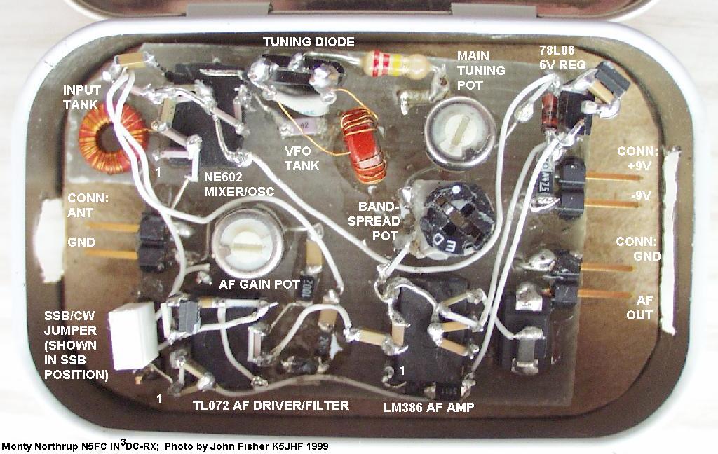
Construction began with a single-sided blank PC board, cut to size to fit inside the box loosely, and narrow enough to accommodate our 2-position connectors. See the photo for construction details. Using "ugly" or "dead-bug" construction, we mounted the 3 ea 8-pin DIP ICs, the TO-92 regulator, and the B104 varactor upside down on the non-clad side of the board, gluing them in place with clear 5-minute epoxy. Then we mounted our three 2-pin connectors flat to the board (again, using epoxy) so that they would face outward toward the ends of the box. Each 2-pin connector was made by snapping off 2 positions from a 36-position-strip of 0.025 x 0.025"sq wire-wrap posts (made by SAMTEC). Similarly, a 3-position jumper field (to become the SSB/CW jumper/switch) was glued vertically. Finally, the pots were epoxied into place, with the adjustment slot accessible from the top.
After mounting the major components, we wound the two inductors. This is a bit tedious, as they required a lot of turns of No. 38 magnet wire. I used a small sewing needle to make the job easier, then a hobby knife very carefully to strip the ends of the inductor wire. I wound each toroid with 3 extra turns, because it's easier to remove turns than to start all over again in the event you discover you're short. By the way, the toroids were not glued in place until all tweaking had been done, at which point they, too, were epoxied, and otherwise sealed with clear acrylic spray.
Once all major components were glued, we endeavored to mount the rest of the components, mainly chip resistors and capacitors. In general, all connections were "tack-soldered". Wherever we needed a ground, we drilled a hole right next to the appropriate pin or component, and ran a wire to the ground plane on the bottom side of the board, where we soldered it. Where possible, the chip resistors and capacitors were mounted directly to the IC leads, held by the solder joint. Decoupling capacitors were mounted as directly between the Vs and G pins as was possible. This takes a little practice, but it's really not that hard. Once one side of the chip is tack soldered, it will stay stationary while you solder the other side, then resolder the first if required. As an aside, I suggest that you always stick with "1206-size" chip resistors and capacitors, which is about as small as one can reasonably handle using this construction technique. For other inter-connections, AWG 30 wire-wrap wire was utilized.
Because the chips have so little mass, the whole resulting assembly is surprisingly rugged and free of microphonics and FM.
Eventually, we had the circuit debugged and working, and needed to install it inside the Altoids box. We glued the PC board to a small piece of cardstock, cut to fit snug in the bottom of the box, yet allowing us to remove the PC board if we needed to. We also glued a piece of cardstock onto the inside of the lid, to provide insulation to any wires or pins that stick upward when the lid is closed.
To gain access to the 2-pin connectors, we cut small rectangular holes in the ends of the box, just big enough to accommodate the mating connectors. We also drilled holes in the lid, centered over the three adjustable pots. The mating connectors themselves are fabricated from a 2-position housing (made by AMP, BERG, and MOLEX) and matching crimp contacts (socket-type). Since I didn't have the correct tool for crimping the contacts (does anybody, ever?), I just used my needle nose pliers and a teeny-weeny spot of solder, but I had to really shape the crimp carefully in order for the contact to insert properly into the housing.
Using this technique, no power switch is required� just unplug the 9V battery's cable from the receiver when ready to power down.
We used a frequency counter connected to pin 6 of the NE602 through a 2.7 pF capacitor to initially adjust the VFO tank circuit into the 40 Meter ballpark. With 3 extra turns on the toroid, we found ourselves oscillating around 6.2 MHz. We removed one turn at a time until we were just below 40. Then, we disconnected the frequency counter, which was adding capacitance to the VFO tank. From now on, we would use the station transmitter operating into a dummy load near the tiny receiver, as a guage of our frequency. We spread and squeezed turns as necessary on the VFO inductor to place our tuning range where we wanted it, then dabbed it with some clear acrylic to keep the turns in place. We found we could shake, rattle, and roll the receiver assembly aggressively with little change in VFO frequency and darned little microphonics.
Observed drift was quite usable. In the first 15 minutes from a cold start, the VFO drifted about 1 KHz, then about 100 hz for the next 15 minutes. We found this quite manageable and saw no need to try temperature compensation.
At first glance, one might think tuning would be too "hairy" using a tweaking-sized screwdriver, but I found it remarkably easy. I'd generally leave the "BandSpread" pot at mid-point, then while tuning slowly with the "Main" pot, I would stop when I heard a signal of interest, and fine-tune with the "BandSpread".
Gain is more than adequate for use with headphones or earphones. When using an un-amplified 15-inch shielded loop antenna, the gain control is typically about 1/3 to 1/2 advanced for comfortable volume levels. In this configuration, sensitivity was adequate to monitor most stateside CW QSOs and many SSB. With the loop antenna, manmade noise was pretty much eliminated. With a full size antenna (dipole), the gain control is typically about 1/8 to 1/4 advanced for comfortable volume levels. Sensitivity was then adequate to hear european and south american DX on CW, and to monitor most SSB nets and roundtables. Amazingly, practically no power line hash was heard with the full sized antenna, even though my TenTec Century 21 had lots of it. With the full-size antenna, however, there was a trace of hum barely audible in the background. (Your results may vary).
While the output amplifier would drive a speaker, it didn't do well with the miniature speakers I tried. But when I used an amplified speaker (the Radio Shack #277-1008 Mini-Amp-Speaker), it really came to life, filling the room with lotsa ham sounds.
Measured current from the 9 Volt battery was 16 mA with no signal and audio gain turned all the way down, and about 35 mA with normal volumes. I haven't measured battery life, but it should be several hours at least.
The entire receiver, earphone, battery, and all its connectors fit into a small padded envelope. I can throw this and the shielded loop antenna in my small suitcase for business trips (buried in clothes), and spend the wee hours listening to 40 meter CW in my hotel room.
I plan to add a keyed audio-mute circuit using an MPF102 FET as the pass element, so that I can use this receiver full QSK with a QRP CW transmitter (That's my next project for the Altoids "Tiny Box")
Be sure to check out the following images, sized for smaller or larger screens: