N5ESE's Junkbox Capacitance Checker

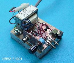
(click on the picture to see larger version)

(click on the picture to see larger version)
I originally saw this circuit posted in an e-mail message forwarded to me recently. I don't know who the original author is. I built this jobber-doo in 3 hours one evening, because I wanted to see if it really worked. Wow! It works way better than I thought possible. If you have a reasonably accurate DVM (Digital Volt Meter) - say, 3-1/2 digits or better - and a few junkbox parts, you should be able to duplicate this as cheaply as I did, and end up with a truly useful and compact tool.
I could have used this on the last project I did. I had some capacitors that were labeled '270'. I coudn't tell if they were 270 pF or 27pF. [Many capacitors nowadays are marked with the last digit indicating the tens multiplier]. Murphy smiled on me that day, and I got lucky and guessed right, but I've been wrong as often on not on previous occasions. Ever wonder what that junkbox variable really is? Herer's the way to find out, quickly and accurately.
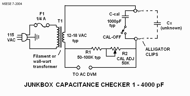
Here's the schematic:

I used a small scrap of 3/4" thick wood to mount the parts, plus a scrap piece of pc board. Layout and construction are completely non-critical. I used a transformer I had robbed previously from an old defunct modem. All the other parts I had in my junkbox. This project cost me zippo!. Fortunately, I found a 1000 pF 1% silver mica capacitor that I had the foresight to pickup some years earlier from Dan's Small Parts for next-to-nothing. It could serve as my calibration capacitor, C-cal. I decided to use a small rocker-switch (stolen from the same old modem) to switch the calibration capacitor in and out of the circuit, thereby avoiding a loose part I had to keep track of. The switch was a pure luxury. For connecting the unknown capacitor Cx, I solder-mounted 2 spare alligator clips to a scrap PC board. This way, I could just clippy in the unknown capacitor, or another calibration capacitor, when I needed to.
The value of all parts is amazingly non-critical. I suggest a wall-wart for the transformer, to make construction that much simpler and to keep from dealing with 115 VAC wiring. Just be sure you get one with AC output (not DC). Anything from 12 - 18 VAC should work (mine was about 17.5V with no-load), but resistor R1 may have to be selected for best range. If you have a 500K pot, substitute it for R1 until you figure out the exact value that works best. I ended up with 50K, made from two parallel metal film resistors. I used metal film because they are more stable than the 47K carbon fiolm resistor I used at first.
To calibrate, apply power and switch in (or clip in) the 1000 pF capacitor. It helps if you have a close-tolerance capacitor like I did, or if you have one (silver mica or ceramic NPO) that you've measured on a lab instrument, because that will make your calibration all the more accurate. For a 1000pF capacitor, adjust the pot to obtain 1.000 VAC on your DVM (1mv = 1 pF). Then switch the C-cal out of the circuit. The reading you get now (depending on the quality of your DVM) should indicate the stray capacitance in your circuit. Mine indicated 3.8 pF. Remember that value, and subtract it from any reading you get on future unknown capacitors. Knowing that, I now re-calibrated the meter for 1.004 VAC (representing 1000 pF + 4 pF). Now I was ready to check a few capacitors.
I dug around the junk box and found three 1% and 2% capacitors that I could use to test the abilities of the capacitor checker. After rechecking my calibration with the 1000 pF capacitor C-cal, I measured the others. The 3000 pF 2% silver-mica capacitor measured 2956 pF, well within its tolerance. A 180 pF 1% silver mica measured 179 pF, likewise well within tolerance. I figured the circuit would not be too accurate at low values, but I was wrong. A 10 pF 1% NPO ceramic measured 9.7 pF, out-of-tolerance, but still within 1/2 pF.
I highly recommend this circuit for anyone who homebrews RF equipment. You won't be sorry!
73,
monty N5ESE