(click on picture above to see larger version)
In my workshed, I have a 12V lighting system consisting of about 60W of high-efficiency LED
lighting, and those are run by 12V lead-acid batteries. Right now, those batteries are charged by
portable line power, but eventually that will be replaced by solar panels. There are two 12V
lead-acid batteries, which reside UNDER the shed, and com into the shed via a panel with two
separate sets of powerpole-type connectors. Each circuit can handle about 4 Amps of load.
Between the battery panel and the actual lighting wiring (on each battery circuit) is one of these
Battery Monitor-Protector units. They are designed with the following objectives:
   - Inserts between the source (battery circuit) and load (lighting circuit)
   - Intended for use with new shed's 100AH Battery System LED lighting (or spare 90AH battery)
   - Provides Alarm/Warning Signal (through Opto-Isolator) for battery voltage below
     11.4V (alarm intended to drive external Beeper; see below)
   - Disconnects load if battery falls below 11.2 VDC (to protect battery from excess discharge)
   - Also disconnects load if voltage rises above 15.5 VDC (to protect load)
   - Expected load < 4A, but circuit itself capable of 12A (heatsinked to diecast box)
   - Note: Fused internally at 15A
   - Total series ON-resistance is max 11 milliOhms (not counting connectors)
   - Could be used with any 12V battery feeding non-motor, non-inductive loads.
   - Optocoupler "FAULT" output may be used to trigger or activate Beeper Alarm.
     Stereo Jack: Tip to Current Limited POS Supply (< 18V; < 5mA, > 0.5mA)
                  Ring to CNTL or GND
                  CHAS to cable shield
   - Current Consumption during Shutdown approx 6.5 mA.
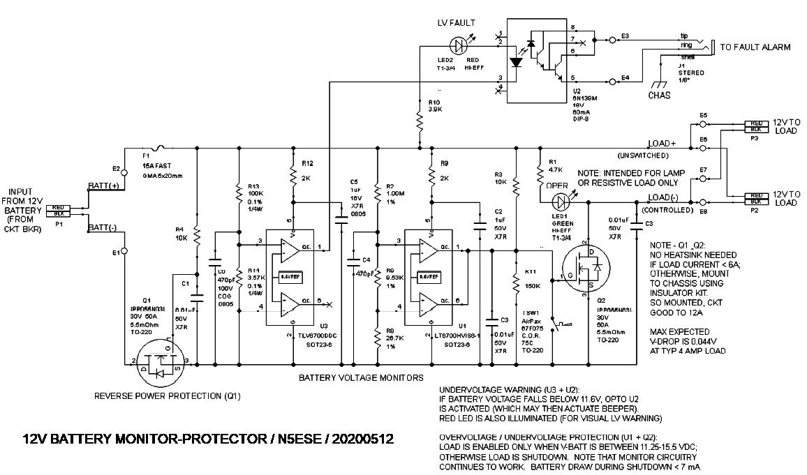
Let's look at the Schematic:

(click on picture above to see larger version)
R4 & Q1 serve to provide reverse-polarity protection. With a 100AH battery, reverse protection is
absolutely required. U3 is the Low-Battery-Voltage Detector. If the battery falls below 11.6V, U3
actuates optocoupler U2. U2's output is available to outside circuitry to actuate a Fault Alarm
(like a battery-operated beeber or light). The alarm is intended to let the operator know that the
battery is low, and needs attention (charging), so that the battery is less likely to sulfate and
degrade. Note: normally, the batteries are float-charge continuously, but those systems can fail
for any number of reasons (like power outages, or a GFCI breaker, or accidental shutoff by XYL -
HIHI). Note a fault does not initiate a shutdown - only an alarm. The battery continues to
supply power to the load.
Continuing with the schematic, U1 comprises a classic "window" comparator. When the battery voltage
is "in the window" (i.e., between 11.25 and 15.5V), as expected, then U1 is "OFF" and R3 pulls the
gate on Q2 high, turning it ON. With Q2 ON, the load (lighting) is connected to the Neg battery
terminal, and lighting is available. However, if the battery voltage goes either above or below
the window limits, U1 grounds the gate of Q2, turning it OFF. With Q2 OFF, the load is disconnected
from the battery. The alarm, however, will continue to sound, drawing only a few milliamps from
the battery.
One other thing can shut down the load and disconnect it from the battery - Thermostat TSW1. TSW1
is mounted to the die-cast box (TO-220 package, as are Q1 & Q2), and if something goes wrong and the
box gets too hot (75 deg C, in this case) then TSW1 closes, shorting Q2 gate to ground, and Q2 is
shut OFF, disconnecting the load. Most likely cause? Unexpected overcurrent (like a short circuit).
Here is a view of the main board, installed in the diecast box (Bud p/n CU-124), and that board's
underside wiring:
(click on either picture above to see larger version)
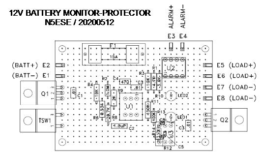
and here is the component layout:

(click on picture above to see larger version)
This system has been operation in my workshed for well over a year-and-a-half, and is doing great.
It's given me an alarm once, when a remote GFCI tripped, and I had no idea until the next day.
Reset the GFCI and all was well - and never lost my lighting along the way.
73,
Monty N5ESE
dit dididit dit