N5ESE's QRP 0-35 Transmitting Inline Attenuator
(click on any picture to see larger version)
(click on any picture to see larger version)
| NOTE: 'N5FC' is my former call. This project was constructed while that call was valid, and you may observe references to it. |
If you have any interest in "milliwatting" (i.e., QRP ops below 1 watt), you're gonna love this project. Encouraged by our results on-the-air with the 10 db attenuator, we endeavored to expand our flexibility, with an attenuator switchable in 5 db steps from 0 through 35 db. Usable throughout the HF range (and maybe into VHF), it allows one to reduce a 5-watt signal in by about 1/3 with each 5db step, until you've divided it by 3000 (that's roughly 1.6 milliwatts! Think you can't have some fun with that? You bet you can! Here's the clincher: cost: less than $25, and a couple of long evenings of your time.
We'll not go into all the details of attenuators in general. You might want to reveiew our other attenuator page for a more generic discussion.
Below is a schematic of the switchable attenuator. Click on the image to see an expanded image with a table of component values.
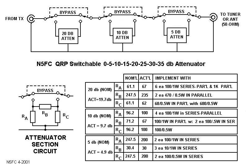
We tried hard to make sure all the parts could be bought at Radio Shack. We ended up using their 1-watt 5% metal-oxide resistors (100 and 10-ohms), available there for a mere 25-cents each (RS 271-152). The remainder of resistors are common 1/2-watt carbon film, also available at Radio Shack. The DPDT micro-toggle switch (RS 275-626, $3) was selected for it's small form factor and it's excellent ratings. Two UG-1094 BNC jacks provide my favorite means of connecting RF.
It's important to shield attenuators, especially when trying to achieve attenuation levels of 20 dB or more. We decided to use the tried-and-true method of building our own cabinet using double-sided printed-circuit board. Dividers of the same material provide compartments shielded from each other, with a single hole in each divider to allow the signal to pass from one section to another. Each piece is carefully cut, then soldered all along joining seams, creating an almost rf-tight box. After sanding the top side evenly against a sanding wheel (or using a block and sandpaper), a cover is fabricated from the same material. Six aluminum spacers determine the inside height of the assembly, and provide the means of mounting the cover. Here's a picture of the assembly before mounting components, with dimensions:
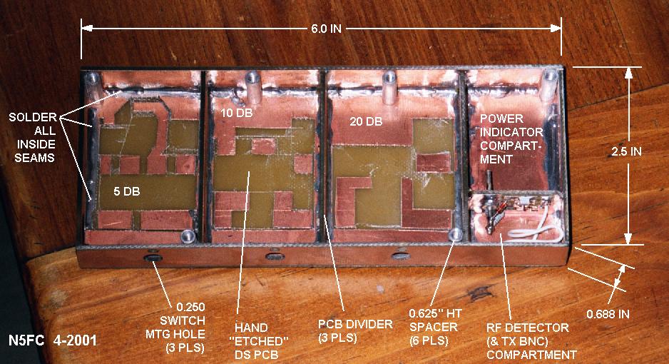
Lands for soldering components were "etched" using a hobby knife (WARNING! WEAR SAFETY GLASSES!), peeling away unused areas of copper.
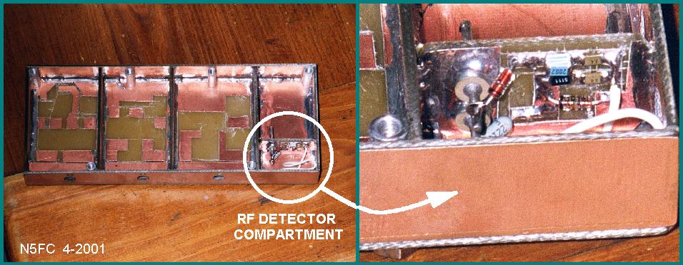
If you looked carefully at the picture, you saw two extra compartments for optional equipment. A small divider near the input jack has components mounted (surface-mount-style) to provide an RF detector (RF-to-DC). The detected RF (now DC), is passed through the compartment wall via feed-thru-capacitors, for decoupling. Though it's not shown, the other compartment will contain circuitry for indicating the input power to the attenuator. The power indicator circuit contains window-comparators which drive one of three LEDs: less-than-2- watts, equal-to-5-watts, and greater-than 10-watts. This allows me to easily adjust my TX for 5 watts input to the attenuator. Here's a detail of the RF detector circuitry. (schematics of the RF Detector/ Power-Indicvator have not been posted yet, while I evaluate the performance and work out some bugs)
Though the device is only sized to handle 5 watts, it may be used for up to 10 watts peak, for SSB or 50% keying. The RF Detector circuit and Power Indicator Circuitry is totally optional, of course, and may be omitted.
Component layout and printed-circuit "etch" is as shown in the color-coded sketch below:
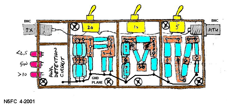
Here's an actual photo of the completed assembly, viewed with the cover off (sans the Power-Indicator circuit):
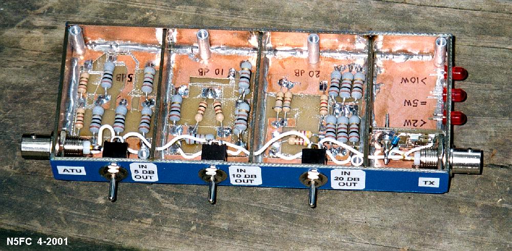
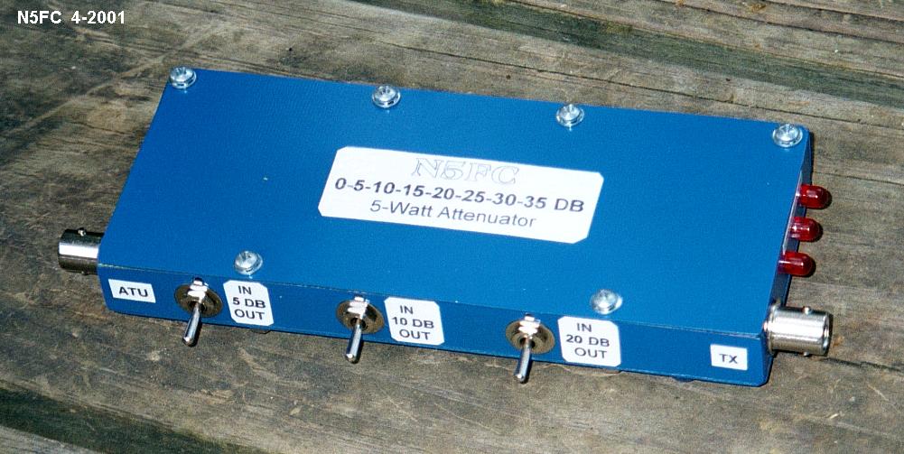
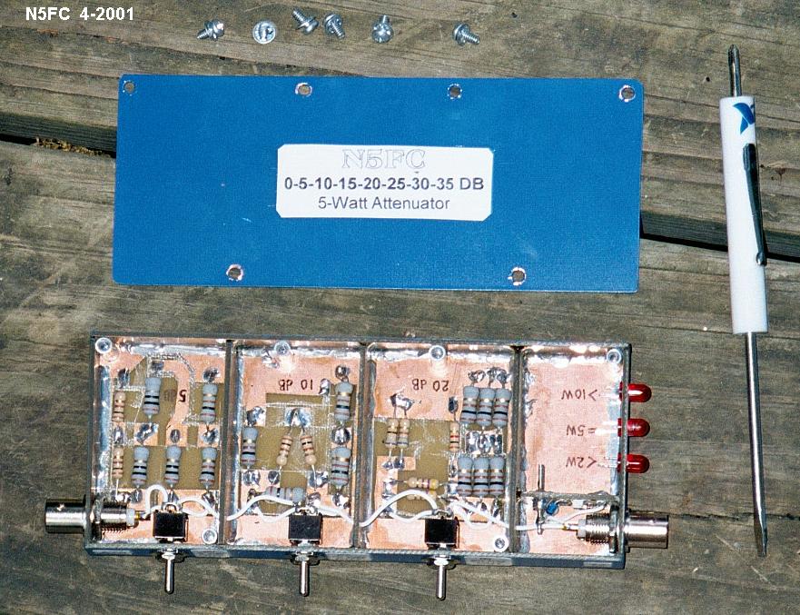
I elected to spiff up the unit with a coat of Krylon Blue, and lables generated on my PC. Here's an overall view with the cover removed:
What kind of results did we get?
We measured the basic DC accuracy of the attenuator at all switch positions, with a 50-ohm load connected to the output:
| SWITCH POSITION | INPUT R (OHMS) | ACTUAL (DB) | |
| 0 db | 51.5 | 0 db | |
| 5 db | 52.2 | 4.85 db | |
| 10 db | 49.9 | 9.44 db | |
| 15 db | 49.8 | 14.15 db | |
| 20 db | 50.1 | 19.42 db | |
| 25 db | 50.1 | 24.10 db | |
| 30 db | 50.0 | 28.97 db | |
| 35 db | 49.9 | 33.65 db |
As can be seen, the basic accuracy of each attenuator section was within 1/2 db of nominal (about 10%), and within 1-1/2 dB with all three sections engaged. We wanted to verify the attenuation accuracy at RF, and I did the best I could with an RF probe:
| SWITCH POSITION | 40-METERS | 20-METERS | 10-METERS | |
| 5 db | 4.68 | 4.74 | 5.04 | |
| 10 db | 9.45 | 9.40 | 9.55 | |
| 20 db | 18.75 | 18.33 | 18.97 | |
I checked the input SWR in "Bypass" and all switch positions. At 30 MHz and below, SWR was 1.1:1 or less. At 146 MHz, it was as shown in the table below (Attenuation on 2 meters was not measured)
| SWITCH POSITION | 2-METER INPUT SWR (OBSERVED) | |
| 0 | 1.3 : 1 | |
| 5 | 1.2: 1 | |
| 10 | 1.55 : 1 | |
| 15 | 1.6 : 1 | |
| 20 | 1.9 : 1 | |
| 25 | 1.8 : 1 | |
| 30 | 1.8 : 1 | |
| 35 | 1.9 : 1 | |
I keyed-down at 5-watts input for 60 seconds. The unit barely got warm. Still, I recommend keeping the input power to 4-watts or less for continuous periods of 30-seconds or more, and not more than 8-watts at 50% duty-cycle (like with CW)
All this is useless fluff if you can't manage a QSO on the air. After testing, I fired up the Century 21, adjusted it for 5W output 20-meters (in the bypass position), and put in 30 dB of attenuation (for about 5 milliwatts out). After about 15 minutes, I happened upon Larry, W0QE in Denver, calling CQ. His signal was well over s9, so I knew I had a chance. I called, and we made a clean exchange. That's 767 miles, for over 150,000 miles-per-watt. Wow! Since he had solid copy, I asked to throw the last 5 db in, for roughly 1.6 mW, and he said he could still hear me in there, with about 75 % copy. Cool!
Can't wait to sail it on 10-Meters with a little solar wind to help ;-)
73, and enjoy! monty N5ESE