N5ESE's QRP Open-Wire/Twinlead Antenna Switch
(click on any picture to see larger version)
(click on any picture to see larger version)
| NOTE: 'N5FC' is my former call. This project was constructed while that call was valid, and you may observe references to it. |
This is one of the most all-around useful projects I've built. It came about when I decided I needed more than the single 40-meter vee. I threw up some other antennas, tested them, and decided I'd like to keep them all around. I prefer balanced antennas that use open-wire feedline along with my trusty antenna match. It quickly got real tedious to swap out open-wire feeders on the rear of the antenna tuner every time I switched to another band. There had to be a better way!. I perused the internet and ham catalogs for a commercial antenna switch that would handle open wire feeders. I found lots of coaxial switches, but no open-wire or twinlead types... not one! Amazing! Am I the only one using open-wire feeders? (I don't think so)
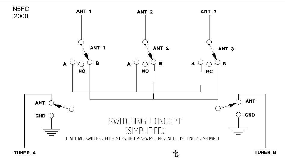
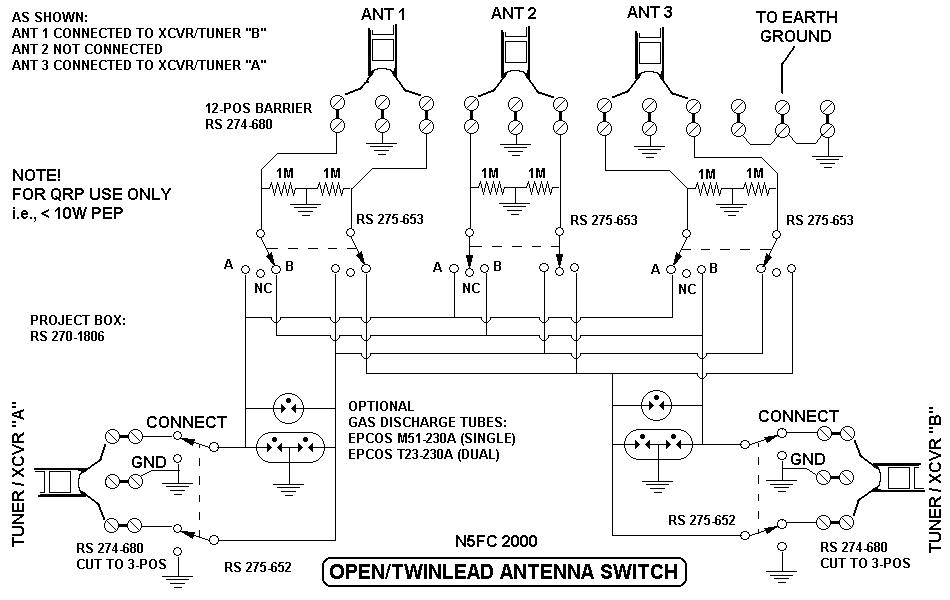
This project grew out of the need for a convenient way to switch open-wire fed antennas. Intended for QRP levels only (10 Watts PeP and below), it provides for selecting any of three antennas to go to either (or both) of two antenna tuners/transceivers. Let me expound on that a little. Using three toggle switches, you can attach any one of the three antennas to Tuner "A", and any one of the other unconnected two antennas to Tuner "B" - and at the same time. You can also disconnect any or all of the antennas, leaving them floating. When floating (unconnected), resistors on each open-wire line to ground provide for static dissipation caused by wind. Two more toggle switches allow the antennas to pass through to the antenna tuners, or to be disconnected from the antenna tuners and grounded to earth. To enhance my version (but certainly optional for the builder), I added gas discharge tubes across the selected antenna, to provide at least a modicum of protection to the receiver front end. Cost? About $20 (not counting the gas-discharge tubes and wire, which I scrounged)
- connect to the "A" tuner's switchOnce selected to go to the "A" or "B" tuner's switch, the double-throw "A" or "B" switch may then be thrown into either of two positions:
- don't connect at all (i.e., float)
- connect to the "B" tuner's switch
- ground the antenna
- connect the antenna to the selected tuner
It's also very handy, when not using some or all of the antennas, to connect all the unused antennas to the the tuner not currently being used, and throw the tuner switch to "ground". When I walk away from the transceiver after an operating session, I make sure all the antennas are grounded. It only involves throwing a couple of switches. And as long as the weather's not severe, I don't worry too much about having one of the antennas disconnected. 1 Meg resistors placed from each feedline to ground bleed off slow static buildup caused by moderate wind, rain, and antenna movement. They are sized to cause less than 1% RF losses under most matching conditions.
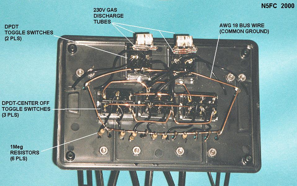
In my version, I added gas-discharge tunes across the feedline to each tuner switch, and from each feedline to ground. I scrounged these gas discharge tubes from old commercial modems, but you can buy them for around $8-12 each. I think they're worth it, for those times when I'm away from home, and I've forgotten to ground my antenna (Hey, it happens...) Rated at 280V, they are a reasonable compromise between protection and operation without distortion. In a 1000-ohm antenna circuit, they should allow about 78 Watts Peak before limiting, and at 5000-ohms, 16 Watts Peak. This is well above the operating specification of 10 Watts-PeP.
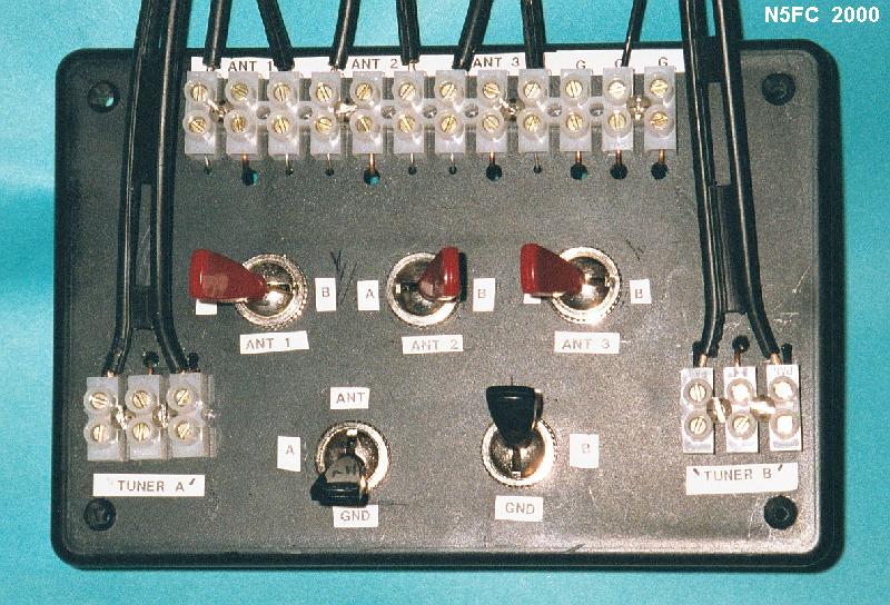
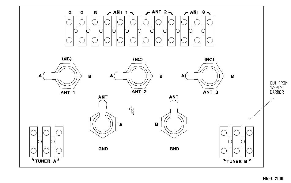
I built my antenna switch in a compact Radio Shack project box, approximately 6 x 4 x 2 inches, and used heavy-duty 60-Hz AC rated toggle switches with large bat-handles. The project box is really easy to drill, and comes with a choice of metal or plastic panel. We used our PC to print lables on sticky-backed paper (obtainable from any office-supply store), which we then applied to the front and side panels. You can see a photo of the front panel at the top of this page. Here's a layout sketch of the main panel:
Click -HERE- for a complete wiring diagram, annotating component part numbers, and showing both sides of the feedlines. [Make sure your browser's page or printer-setup is set for "landscape" mode to assure best printing]
I used AWG 18 solid bus wire inside the unit, and arranged it to minimize losses and minimize disturbing the natural SWR of the feedline. I have not actually measured losses. Likewise, grounds are arranged to minimize inductance. The barrier strips are of the "euro" variety, because they don't require you to prepare the mating wire (other than to strip it about 1/4 inch). A wire is fed from one side of the barrier-strip terminal through a 1/16-inch hole in the project box, to the inside, where it is routed to its connection point. Here's an image of the internal layout:
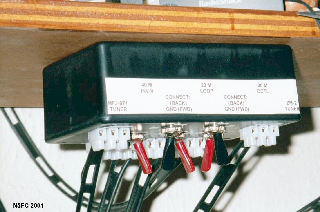
I mounted my antenna switch upside-down under the first shelf at my operating station, as shown (and circled) in the image below. This is a very convenient place for me to swithch antennas when band-hopping or antenna comparing.
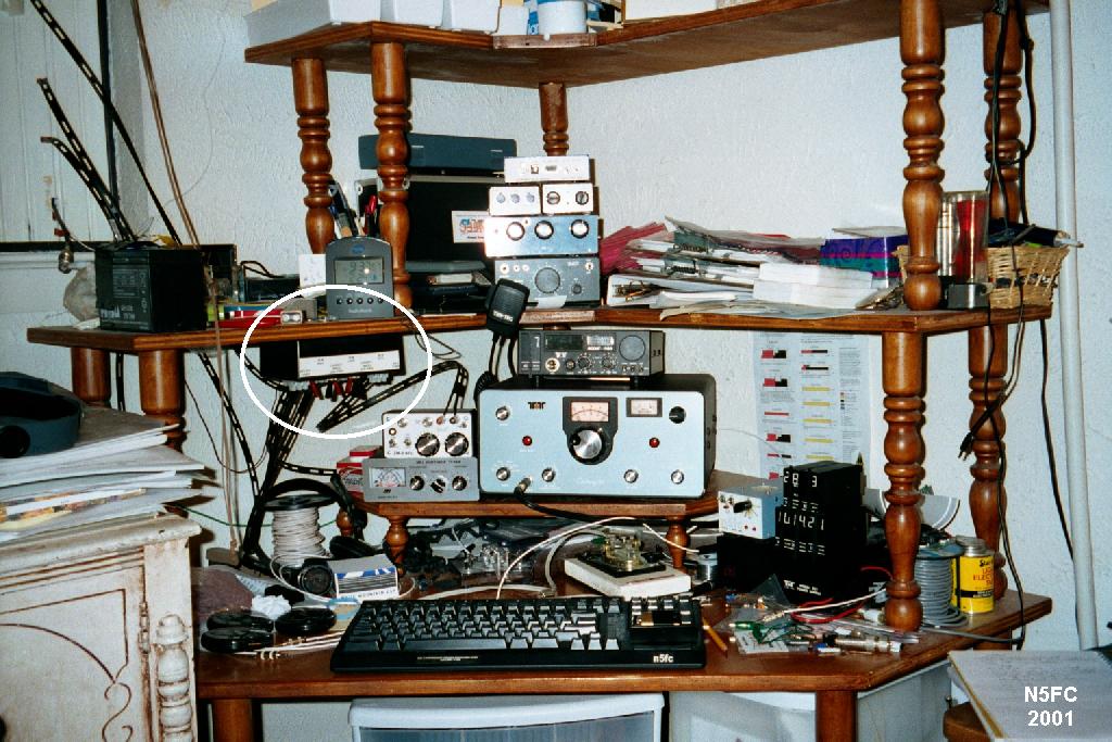
And here's a close-up of my (operating) view of the antenna switch:
The QRP Open-Wire/Twinlead Antenna Switch is a great time-saver really easy to use, and I think you're going to like it a lot.
Enjoy! and 73!
monty N5ESE