(click on picture above to see larger version)
A few years ago, I bought a relatively inexpensive GPSDO (GPS Disciplined Oscillator) on eBay
from Chinese seller rf-experts (- see their ad here -). This is a terrific device, a stationary GPS
receiver which provides NMEA time streams (ASCII TTL) and a 1 PPS (pulse-per-second) Output. Given
the super accurate PPS (typically accurate to within 1 nanosecond, that pulse can be used (over a
long period of time, like tens of minutes or even hours) to "discipline" or "lock" a local 10 MHz
oscillator to within 0.1Hz (or, more typically, an order of magnitude better), That's pretty
doggoned close to "close 'nuff"!
In the GPSDO, that 10MHz oscillator is generally provided as a sinusoidal output that can drive a
50-Ohm load (via coax) to around 0.25-1V (pk-pk). And because it's so rediculously accurate,
it can be considered a secondary standard (reference) for calibration of test equipment or as
a reference input to a frequency-critical device.
I have a few pieces of test equipment that would accept a 10 MHz reference. One is my HP 8368
Spectrum Analyzer, and one is my HP 8640B Signal Generator. Both will accept a 10 MHz
reference to drive their internal synthesizers. And I have a homebrew 600 MHz Frequency
Counter (currently under construction) that will accept a 10 Mhz Reference as an alternate
timebase. So I potentially have 3 pieces of test equipment that could benefit from this
super-accurate reference, but only one GPSDO (with one 10MHz output).
So what I needed was a dedicated 3-channel gain-of-1 amplifier that would drive 3 independent
50-Ohm loads *** and *** preserve the quality of the GPSDO 10MHz reference.
Said another way, what I needed was a good-quality low-distortion Video Amp for 50-Ohms
(instread of 75-Ohms as with most video). Oh - obviously - and 3 outputs.
Most video amplifiers available commercially are designed to drive 75-Ohms. This is fine for
cameras and monitors, as they are also designed for 75-Ohms. For RF devices and RF test
equipment, they're almost always designed for 50-Ohm termination (and transmission lines), so
they require that a driver amp be about 50% heftier. So we were on a quest to find a triple
amplifier with hi-res video bandwidth and capable to driving 50-ohm loads.
The LT6557 fits the bill. This is a 500 MHz broadband Amplifier with fixed Gain (Gain-of-2,
which will become Gain-of-One when we apply termination). And it requires a single 5VDC
power supply. And it is capable of delivering the signal we are trying to amplify, AC-coupled,
into a 50-Ohm load.
So our task is to supply clean power, and preserve the input signal while providing for three
AC-Coupled outputs to three BNC connectors which will ultimately be terminated in 50-Ohms.

(click on picture above to see larger version)
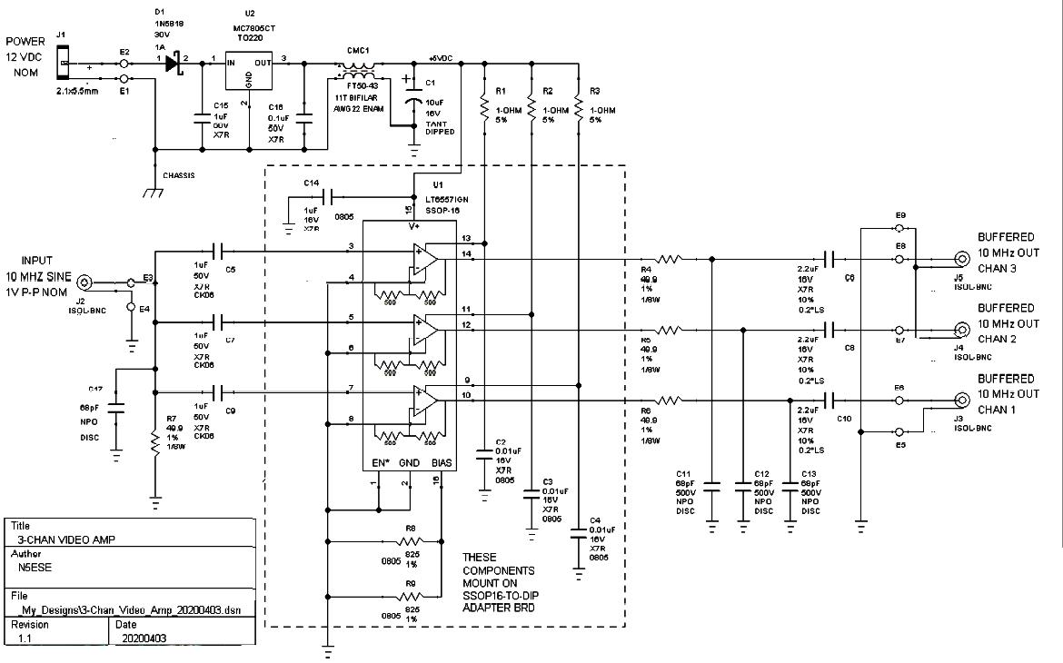
In the above schematic, notice first the three amplifier sysmbols, then take note of the
dotted line around that chip and its supporting components. In our construction, that
boundary will define a subassembly built on an SMT-to-DIP adapter board (which we then
modify slightly). This allows us to place all VHF/UHF decoupling components where they need
to be - close to the amplifier ship. This is a 500-MHz device, which we are using at 10 MHz,
but which we want to be absolutely stable, so by putting this in its own subassembly, we are able
to follow the manufacturer's guidelines for best layout and operation (or nearly so).
These chips (somewhat uniquely for broadband amps) are voltage op-amps with fixed Gain-of-2
by virtue of built-in resistors. This gives them a dynamic output impedance nearing 0-Ohms
(like an ideal voltage source) but then you are required to place a resistor in series with the
output to define the output impedance and characteristic impedance of the transmission line
(i.e., coax). In our case, that is 50-Ohms. That series resistor stabilizes the amplifier as well,
so that it can stably drive the capacitance it will see in a coaxial cable. In our case,
we will also provide a capacitor to ground at the output of that series resistor, which
then forms an R-C filter to define the upper Fc(-3dB) of our system at 46 MHz.
NOTE:The lower Fc(-3dB), as shown in the schematic (and as built) is really too low
(down below 10 Hz) and could allow some jitter from common mode induction and current loops
and such to be introduced into the signal. That becomes a miniscule distortion in the sinusoidal
signal that won't be seen, but could lead to jitter which degrades the accuracy.
I think I probably took those value from the manufacturer's reference design (without thinking
it through). Those coupling capacitors, both input and output (re C5 thru C10) should really be
0.047uF/50V/COG-NPO (like Murata RDE5C1H473J2K1H03B or TDK FA16C0G2A473JRU06).
The COG/NPO material will enhance stability and prevent the possibility of microphonics, and
the lower Fc(-3dB) will end being in the ballpark of 0.1 MHz (well away from our signal, but
also from unwanted low-frequency effects).
Also from the schematic above, notice the input power supply. With an amplifier such as this,
we need to do everything we can to ensure that the amps get clean power with nothing that
might introduce distortion. To that end, we provide a pretty conventional linear 3-terminal
regulator, and then some extra filtering to clean up whatever might have snuck through that
regulator. CMC1 and C1 clean up any artifacts that might wiggle in between the chassis and
our local common, and then 1-Ohm resistors with 0.01uF capacitors (another R-C filter)
further clean up the supply voltage to each amplifier.
We packaged this into a 4.4"L x 2.4"W x 1.2"H Hammond 1590B die-cast aluminum box, which will
provide full shielding.
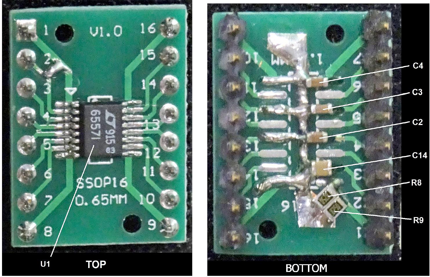
As mentioned earlier, the LT6557 mounts onto an SMD-to-DIP adapter board, with mods. We chose
an UXCEL 28180Z05-02P adapter board (re Amazon ASIN B07FK2X3MS), which has an
SSOP-16 SMT pattern on one side, and a SO-16 pattern on the flip side. This allows us the clever
ability to mount our chip (SSOP-16) and mount some other components on the opposite side. Yay!
Turns out a few semi-tricky mods are required here, to do this "right". We'll scrape off some
mask and provide a jumper betwwen Pin 1 and Pin 2 on the SSOP side. Then on the opposite
(SO-16) side (the larger pattern), we'll create a little ground plane down the centerline
of the pattern with a larger pad on each end. We do this with some copper tape (the kind
with adhesive - you can get at Michaels or Hobby Lobby). It's a little tricky, but I got
it "good 'nuff" on the first try. Using that new ground plane, we can place our 0805 SMD
capacitors (VHF/UHF decoupling) as shown below. Keep in mind, if you mount the chip on
the SSOP-16 side (do that first) with pin 1 to its pin 1 position (as of course you would),
then the numbers silkscreened on the opposite side (the SO-16 side) will be reversed. That
is, silkscreen Pin 1 on the SO-16 side will actually be Pin 16 on the SSOP (chip) side.
Scrape mask away as necessary to make good solder joints to the respective SMD components.
And be sure the DIP Pins end up sticking down on the SO-16 side, so that when the subassembly
is installed to the main perf board, the chip ends up visible from the top. Hubba hubba.

(click on picture above to see larger version)
(click on picture above to see larger version)
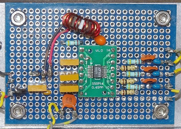
When that subassembly is done and triple-checked for shorts/opens/continuity, it can be mounted
to the main perf board, which is shown below:

(click on picture above to see a larger, annotated version)
On the underside (not shown above), wiring is completed using small (AWG22) bare wire,
point-to-point.
And below, note that the all BNC connectors are isolated from the box. 12V power, however, is
grounded to the box.
(click on picture above to see larger version)
(click on either picture above to see a larger version)
Our GPSDO is normally powered by an independent 12V/35AH SLA Backup Battery. Because the
backup system is normally charged by a line-operated power adapter/charger, the voltage
applied to the GPSDO (and distribution amp) is usually the float charge voltage: 13.8 VDC.
But during loss of power, that can drop to as little as the battery cutoff voltage of 11.6V.
At 13.8V supply. the GPSDO power consumption is typically 150 mA, and the 3-Channel Distribution
Amp consumes about 71 mA. Aggregate, then, is 221 mA. At 11.6V, that aggregate climbs by an
additional 25 mA. So the backup supply provides about 3 days of backup power such that the GPSDO
does not lose lock. Since the devices being supplied 10 MHz reference are not backed up,
one might be tempted to power the distribution amp separately, and save/increase backup
time. But such a scheme might introduce more artifacts in the output, as the power supplies
being different might introduce ground loops. We suggest it is best to run GPSDO and distribution
amp from the same power source.
We tested our unit by connecting it to the output of the GPSDO via 50-Ohm BNC-to-BNC patch
cable. Below, we see an image of what we observed on our oscilloscope for Channel 1
using a 50-Ohm termination (1Vp-p In, 1Vp-p out). We are unable to test actual jitter -
we simply don't have that capability.
(click on picture above to see larger version)
You probably won't run into ground loop issues if you power all the equipment from the same
branch circuit (i.e., power strip). Nevertheless, the possibllity of ground loops continues
to exist between different pieces of line-powered test equipment being fed the 10MHz
reference signal. If this is noticed, a solution would be to break the ground loop using
a 1:1 RF transformer inline with the BNC cable going to the test equipment. This could
easily be done in the distribution box, between the coupling capacitor and the output BNC.
Use a 1:1 RF transformer. A good starting place would be an Amidon FT37-43 ferrite core
with 8 side-by-side turns AWG 28 enameled wire, forming isolated primary and secondary.
Commercial versions of this exist, like the Minicircuits FTB-1-6*A15+, but at $63/ea,
they're a tad pricey.
73,
Monty N5ESE
dit dididit dit