as built by Monty Northrup, N5ESE
If you're looking for the 13xx Mods & Fixes page, look -here-
If you're looking for the 13xx Mods & Fixes page, look -here-
| NOTE: 'N5FC' is my former call. This project was constructed while that call was valid, and you may observe references to it. |
I wanted to participate in Field Day 99 as a field-portable single-op QRP station, and wanted to construct a single-band QRP rig just for that purpose. I really wanted to homebrew my own rig, but when I realized (after months of procrastination) that it was just three weeks before the big weekend, I decided that a kit was going to have to suffice. I perused the Internet for possibilities, reading reviews where they were available. The kits seemed to fall into 4 catagories: dubious designs, too simple or low-power for my tastes, way too expensive, and "just about right". Of the "just about right" kits, the TenTec 1340 looked like the best choice because it used proven superhet techniques, had a 4-crystal IF filter, 3-4 watts of power output, was easy on battery power, had full-QSK, and cost $95 (which included the cabinet). You can see the 1340's specs at TenTec's amateur radio site -here-
If you want to read about modifications and fixes for the 13xx series, look -here-
In 2009, Chuck Adams, K7QO, did a marvelous PDF on assembling and testing the TenTec 13xx series and you can find it archived - here -
If you want to review the Assembly manual, you can find that archived as "1340" at Mods.DK.
Update September 2001: When TenTec put the 1300 series kits on sale for $85 this fall, I bought two more kits (the 1315 and 1330 for 15 and 30 Meters, respectively). After a fury of building activity (and modifications), I took all three completed transceivers on vacation to the mountains of New Mexico. All three performed superbly, and cemented my belief that this rig is one of the best bargains in ham radio today. The highlight of the trip was my QSO with JA1NUT, from atop an outcropping on the ridge above NM HWY 126, at 8500 feet, using the 1315 at 2.5 Watts running on 9 internal AA batteries (see the mods page). See the proud king-of-the-mountain below:

My 1340
By the time I got the kit, I only had two weekends to build it. I had heard TenTec's kit-manuals were good, and I found them to be quite adequate. I had not built a kit since before Heathkit's demise, so I was interested to see what was considered "good" nowadays. The instructions came in a spiral-bound manual, with copious diagrams, and all the information I needed to put it together. The assembly was divided into multiple phases. Typically, at the end of each phase, some testing and/or tweaking was suggested.
First (Pase 1), we assembled the DC power and keying circuits, then tested that it worked. Phase 2 was the 4.0-3.85 MHz VFO. Here, one shortcoming was noted. In an effort to make counting turns on the hand-wound iron-powder cores easier, they confused the heck out of me. The accompanying picture did not match my interpretation of their explanation, and so I had to take a stab at what they meant. I'm not going to try to explain it either, as that would only add to the confusion. My only recommendation is to comply with the literal interpretation of their written explanation. [NOTE: This still holds true, but you can see my feeble attempt at clarification - with pictures - on the Mods Page]. The progress test for the VFO requires that you squeeze turns on the VFO tank coil to place the tuning range where you want it. A frequency counter is useful here, but you can use a general-coverage receiver in lieu. I had planned to add the "Freq-Mite", a tiny, $20 PIC-based CW frequency-annunciator (and one of the bargains of the 20th century) to my kit, and since I didn't have a bench-type frequency counter, I used the Freq-Mite and a 9-Volt battery to align my VFO. Phase 3 assemble the Transmit Mixer, and afterward some keying and tweaking was done to verify it worked. Phases 4 and 5 assembled the Receiver IF, the BFO, and part of the Audio circuitry. At this time some receiver alignment was accomplished, adjusting the BFO for a reasonable audio note, and tweaking some coils for peak signal from a signal generator, external transceiver, or on-the-air-signals (I used my Century 21 and a dummy load). Phase 6 assembles the AGC circuit and audio preamp, and tests them. Phase 7 assembles the transmit-driver and power amplifier stages, and the output low-pass-filter. You are given the option of testing the transmit-driver stage prior to placing the power-amplifier, but I opted to skip that interim step, and test the entire tramsmit-chain with a dummy load. Here, I ran into some trouble. The transmitter worked fine into a dummy load (putting out about 3.5 watts), but became unstable when operated through a tuner into an end-fed wire. I thought the final transistor (a 2SC2166) might be bad, so I substituted a "hotter" NTE236.... Big mistake... I now had 5 watts output, but I also had low-frequency parasitic oscillations, which could even be heard in the receiver. I changed back to the original final transistor. I tried it on the regular outside dipole, and everything was stable. Tried it on the end-fed wire... not stable, even though the SWR meter read 1:1. Oh well, as long as it was stable on a doublet, I was satisfied, because I planned to use an inverted vee for my field-day antenna. [NOTE: See Mods Page for info on fixing this]. Phase 8 of the assembly put everything in the cabinet, and aligned the RIT. I added a BNC connector for the output, an extra SwitchCraft-type coaxial power jack, a "stereo" 1/8" phone jack (for stereo headphones, wired monaural, of course), and the Freq-Mite CW annunciator (with it's attendant push-button)
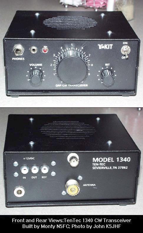
Here are some pictures:

The rig performed splendidly for me on field day. I was worried that I would have to fight and claw for contacts, using only battery power and 3 watts to the hastily erected inverted-vee. But my worries were unfounded, and I made 170 contacts before running out of energy after 18 hours of operating. All of that operating was done on one solar-charged 12V, 7AH gel-cell battery, which was still reading above 12 volts when I finished. [ Well, actually, I placed a NiCad D-cell in series with the 12V battery, to boost the input voltage to 13.5 when the 12V battery got below 12.2 Volts, so that I could keep the power output above 3 watts]. The receiver was plenty sensitive for 40 meters, performed exceptionally well with adjacent strong signals, and had great single-signal selectivity (a real luxury for an operator who's used to the direct-conversion receiver in the Century 21)
73,
Monty N5ESE
dit dididit dit