I recently acquired a 1980s-vintage Kenwood R1000 Receiver at a swapfest, then ended up spend two weeks of my life fixing it. In going over the circuitry in minute detail, I noticed there was no input protection at the antenna. I needed to do something, because I wanted to leave this on a local antenna continuously, for WWV monitoring and general SWL'ing.
In recent years, because of the increased attention to surge protection for GHz logic and RF IC's, tiny diode and zener-based surge devices have become increasing available (and cheaper and cheaper). Likewise for GDTs (Gas Discharge Tubes).
It occured to me that we could devise a very simple module to incorporate into any HF receiver front end that would be easily installable, and cheap and effective as well.
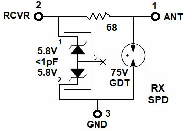
Here's a schematic of what I came up with:
As you can see, it's a very simple device. The antenna connects to the right side, the receiver antenna jack on the left. A large static surge coming from the antenna gets shunted to ground by the GDT (which generally triggers at around 75V). The GDT takes the brunt. For lesser static discharges, the 3-terminal zener device limits that to around 6V, along with the series resistor. The 68-ohm resistor can cause up to about a 3 dB loss in incoming signal, but I guarantee you'll never know it.
This all ends up costing about $2 per copy for a LOT of protection. Here's the Parts List:
Parts:
-------
1 ea 68-Ohm 5% 0603 (or 0805) SMD Resistor; Vishay/Dale p/n CRCW060368R0JNEA
1 ea Diode Array (Back-to-Back 5.8V ultra-low capac Zeners) in SC-75-3 package; OnSemi p/n ESDR0502BT1G
1 ea 75V/2KA GDT (Gas Discharge Tube, axial-leaded; Epcos/TDK p/n B88069X8091B502
1 ea SOT-23 Flippable SMD-to-DIP adapter board; p/o Adafruit p/n 1230 (or P1230)
Note: all the above parts are available at Mouser ( https://www.mouser.com )
The Adafruit adapter is intended for mounting one or two SOT-23 (surface mount) devices. We use it

(click on the picture above to see larger version)
Above image is a composite illustration ONE double-sided board. The board has 2 ea SOT23-3 patterns
on one side (left) and the flip side has 1 ea SOT23-6 pattern. Pins 1-2-3 refer to the SAME
plated-through holes. The 0603 (or 0805) SMD Resistor will mount where shown on the left view (i.e.,
between Pin 1 and Pin 2). The SC-75-3 (tiny 3-terminal diode-array chip) will mount at the
location shown in the right view (on the flip-side of the board). Pin 1 of the chip solders to the
pad going to Pin 2 of the board. Pin 2 of the chip solders to the pad going to Pin 3 of the board.
Note that Pin 3 of the chip does NOT solder to anything. The axial-leaded GDT (Gas Discharge Tube)
mounts using the Through-holes, Pin 1 to Pin 3 on the board, with Pin 3 designated as the GROUND
point. The leads of the GDT then become our connecting wires for installation into our receiver.

(click on the picture above to see larger version)
In the R1000 receiver (remember? that's where we started), 3 of these were required because we had
3 antenna terminals. The typical receiver has only one. Electrically, we inserted these as
illustrated below:

and the real world installation (under the hood) looks like:

(click on the picture above to see larger version)
73,
Monty N5ESE
dit dididit dit