N5ESE's Dual-band Version of the
SWL Rock-Mite CW Transceiver
click on the picture to view larger image
| NOTE: 'N5FC' is my former call. This project was constructed while that call was valid, and you may observe references to it. |
I love seeing how much functionality can be packed into a small electronic package. So when I heard that Dave Benson, K1SWL, and Small Wonder Labs was offering a tiny single-band CW transceiver kit called the Rock-Mite for just $25, I knew I had to have one... er... two. Currently offered in two versions, 20 and 40 Meters, it seemed the ideal candidate for a minimalist dual-band rig. In this web page, we'll discuss our experience building the Rock-Mites, and show how we packaged it to become a tiny dual-band CW transceiver.
If you'd like to see what many, many others have done with the Rock-Mite, visit N0RC's Rock-Mite web page. Lots of Mods and enhancements featured there, too.
The Rock-Mite is a "minimalist" rig in the finest tradition of the QRP philosophy "KISS" (Keep It Simple, Stupid). That is not to say that it is a poor performer. I have built direct-conversion receivers based on the NE602 active mixer and a follow-on audio amplifier chip, and my experience has taught me that they never have enough gain to provide adequate headphone volume. When I saw that this receiver used that schema, I was understandably skeptical, but somehow Dave Benson has managed to overcome the typical shortcomings completely, without complicating the circuit. I think I can safely say that he is the master of optimization, and that's a good thing to be when engineering a very simple circuit.
The Rock-Mite is a single-frequency rig, with the transmitter and receiver fixed tuned to just below the QRP Calling frequency of 7040 KHz (or 14060 KHz for the 20 Meter version). Because a fixed offset of about 700 Hz is provided between the receiver and transmitter frequencies, a feature was added to manually swap the RX and TX frequency. This prevents the unpleasant situation of having someone call you zero-beat at the receiver frequency, with no recourse to tune away. A Crystal-controlled Colpitts Oscillator provides both the transmit and receiver injection. A bipolar transistor buffer stage provides drive to the bipolar final amplifier, which provides about 3/8 - 1/2 watt RF Out (depending on the supply voltage). A 5-element pi-network provides matching to the 50 ohm load, i.e., your antenna or tuner.
It's amazing what features Dave has managed to pack into a 2 x 2-1/2 inch pc board assembly. Would you expect automatic T/R switching in a minimalist $25 rig? Including receiver muting and sidetone? Well, you have it with the Rock-Mite! How about a built-in iambic keyer capable of 5 - 40 WPM? It's yours, all on the same tiny board! All these are possible due to the clever use of an 8-pin pre-programmed microcontroller chip.
The Rock-Mite arrives in a padded envelope, with a four-page instruction sheet (2 sheets, both sides). Here's a picture of the kit, before starting construction
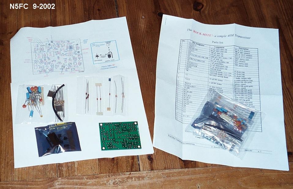
Instructions were clear, and the parts list, schematic, and parts layout drawings were accurate. Beginners might have a little trouble figuring out how to connect external wires and controls because those details are pretty much left to the user, being only alluded to in the narrative.
My first board went together in about 3 hours, from start to test, so this is an easy evening project. Packaging will eat up a little more time, depending how elaborate you want to get. For those who don't want to fabricate their own enclosure (or use an Altoids box HI HI), a first-class machined (yes, machined!) and anodized "MityBox" is available for $20 from The San Luis Machine Company
Here's a picture of both the 20 and 40 Meter versions of the Rock-Mite, prior to testing:
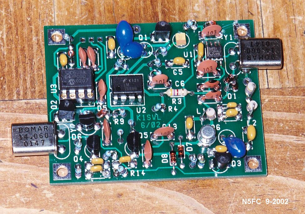
Those with a sharp eye will notice that these are not exactly "stock"... we'll explain why in the next section.
I really wanted to package these in a unique way, and as compactly as possible. In order to accomplish this goal, I decided to do three things:
In order to lower the overall height of two stacked boards, I modified the individual boards (during assembly) by substituting lower-profile components wherever parts stuck up above the board in excess of 5/16 inch. As I have a pretty good junk box for homebrewing, this did not add to the cost for me. The following list summarizes these changes:
This all allows the two Rock-Mite boards to be stacked together, using four 5/8" long (x 3/16" dia) male-female threaded spacers, which I salvaged from some discarded computer equipment. The vertical height of the stack is less than 1 inch. Here's a view of the stack from the output end:

And here's a view of the stack from the input end:
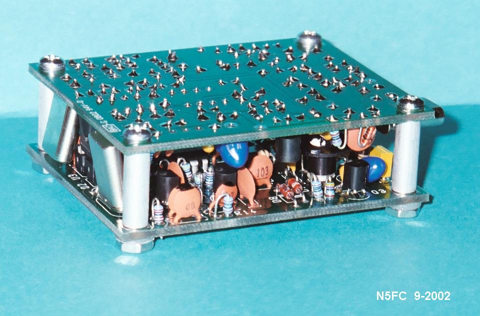
Notice here that the Y2 crystals are angled outward, because they're just a smidgeon too tall to fit between the 5/8" spacers. Also, notice the "tophat" heatsink mounted on the metal-can 2N2222A (on the right, bottom board, just behind the two blue resistors, and to the left of Q3). The tophat exceeds the 5/16 profile slightly, but it so happens that the components on the mating board are well under the profile, hence no fit interference takes place. Almost like we planned it HI HI (we didn't).
The enclosure for the dual band Rock-Mite is homebrewed from double-sided 1/16-inch pcb stock. This is a nifty way to make a strong, custom-sized enclosure, and I've used it on several projects. The technique is to carefully cut each panel of the enclosure, then use a medium-to-high wattage soldering iron to run a solder-bead along any right-angle joints, forming an amazingly strong construction. TIP: use a 3M scrubbing pad to removed oxidation from the copper first, and apply a thin film of acid-free flux just prior to soldering, and this will make the process go much more smoothly. The trick in this techniques is keeping the panels at right-angles while soldering, and it may take a little practice before you acquire the finesse needed. I usually tack-solder the joint at two ends first, so I can adjust it if necessary; then, I run my solder bead.
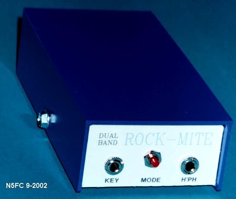
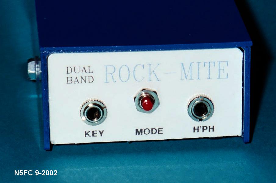
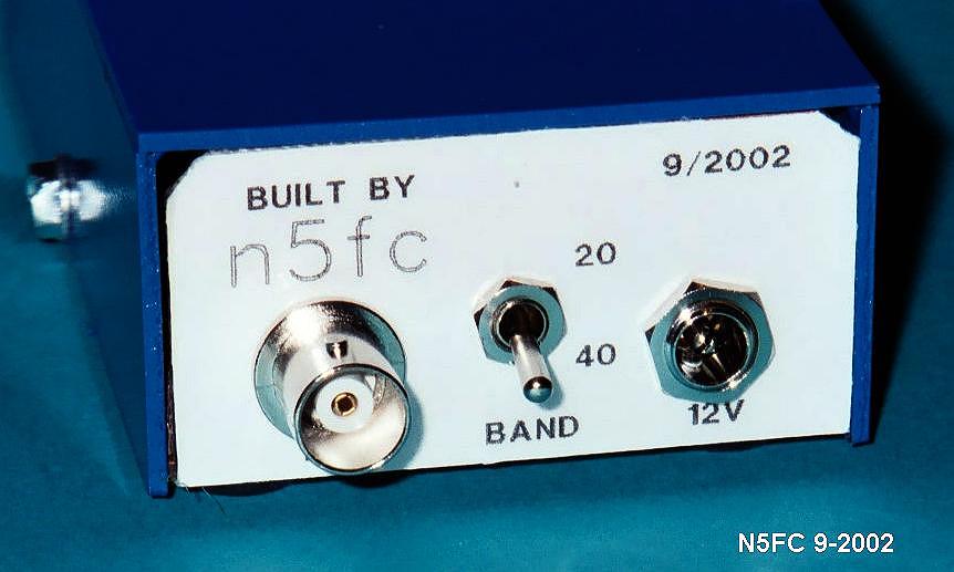
Using this technique, we constructed a chassis 2-1/4"W x 4-1/4"L x 1-1/8"H (O.D.). The chassis consists of a bottom plate, two end panels (which form the front and rear panels), and two 1/4" high side panels (for addditional rigidity). We also constructed a slip-on top cover, which consists of two side panels (1-1/4" H, O.D.), and a top plate. The top cover is held in place with two No.4 x 1/4" sheet metal screws, on on each side, which screw into the chassis' side panels.
To make it look "purty", we constructed lables on our PC, printed to sticky-back paper (mailing lable paper, available in any office supply store), and applied them to the front and rear panels prior to mounting controls and connectors. Then we painted the chassis (outside only) with clear acrylic lacquer, and the top with bright blue enamel.
In order to consolidate connectors and controls (in other words, to avoid having two complete sets of connectors and controls), we use a DPDT toggle switch and some external diodes and wiring to connect the two boards together. The result is what appears to be a dual-band Rock-Mite. Here's the wiring diagram:
Notice that the bandswitch is a DPDT-CO subminiature toggle switch (RS 275-620). It serves the dual purpose of bandswitch and power switch, with the "center-off" position being exactly that.
The two resistors (10-20 ohms each, typical) at the headphone jack prevent an accidental short circuit in the event someone plugs a 1/8" mono plug into the stereo jack. You could certainly leave these off if you like, connecting both the tip and ring terminal together.
One note before I get questions: to reduce the possibility that RF feedback via the power lines occurs, causing hum and poor receiver performance, special care was taken to shield and decouple the power. To do this, RG-174 miniature coax was used to route power from the bandswitch to the individual boards, with the shield connected to the ground plane of the rear panel (so that there is a low-impedance path to the Antenna jack's ground). On the end nearest the board, the shield is left unterminated (i.e., open); this provides good electrostatic shielding. Also, at the DC Power Jack, the incoming DC is decoupled with a 0.01 uF monolithic capacitor, to keep radiated RF from entering via the power line.
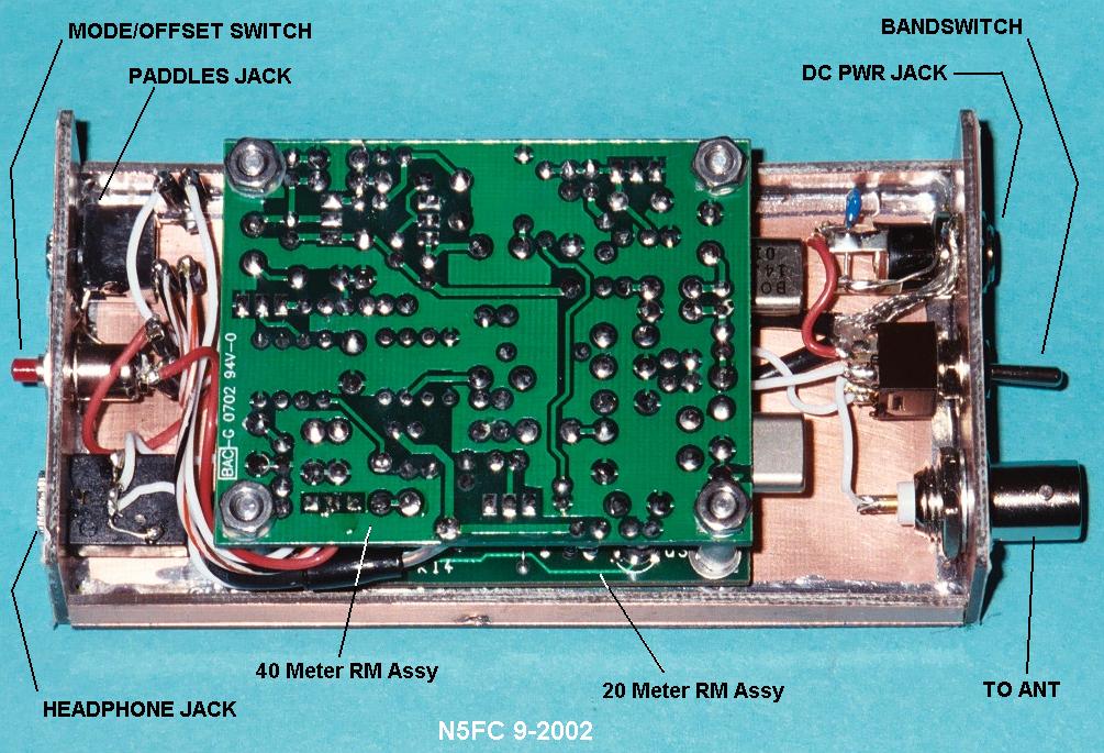
Here's a view of the completed wiring, showing the board stack, chassis components, and layout:
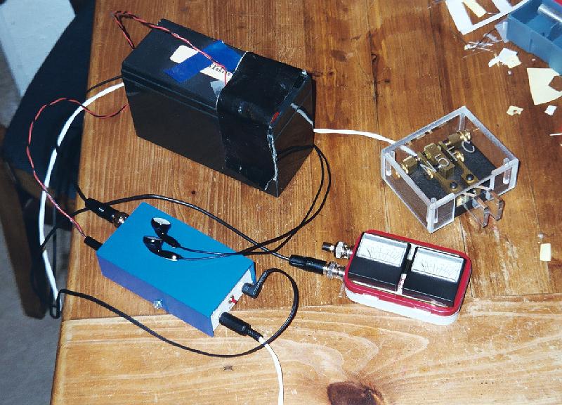
Operation is straightforward. Hook up your antenna or antenna tuner, power supply (I used a 12 Volt gel-cell battery), earphones, and your key or paddles. Use the bandswitch to select your desired band. Assuming everything works, you should here some band noise or signals. Key to tune-up or transmit. Pushing the front panel pushbutton once quickly will reverse the offset. Answering CQs can be tricky... you don't really know which side of zero-beat you're on. Here's some guidelines: If the pitch of the signal is is very low (less than 350 Hz), push the button once and call the station. If the pitch sounds somewhere around 500-1000 Hz (medium pitch... your on your own here HI HI), push the button once. If the pitch gets lower, push the button again to switch it back, and give 'em a call. If, on the other hand, it gets higher in pitch, you're probably too far off-frequency - go ahead and call, but don't be surprised if the other station doesn't hear you.
When calling CQ with your mighty 1/4-watt, expect everyone within several KHz to come a' runnin' when they hear your booming signal. When listening after a CQ, push the button once in a while to see if someone is off-zero-beat calling you, but always switch it back prior to transmitting, so they don't lose you (hey! how could they lose you?)
Hereare some measurements I took to assess my Rock-Mites' performance:
| ROCK-MITE RECEIVER PERFORMANCE | ||
| Blocking | MDS | |
| 40 M ROCKMITE | > 1 V | ~ 0.3 uV |
| 20 M ROCKMITE | > 1 V | < 0.25 uV |
| ROCK-MITE TRANSMITTER PERFORMANCE (12.15 VDC) | |
| Power Output | |
| 40 M ROCKMITE | 400 mW |
| 20 M ROCKMITE | 375 mW |
| ROCK-MITE TRANSMIT FREQUENCY | ||
| TX FREQ 1 | TX FREQ 2 | |
| 40 M ROCKMITE | 7039.04 KHz | 7039.80 KHz |
| 20 M ROCKMITE | 14058.88 KHz | 14059.70 KHz |
| ROCK-MITE CURRENT CONSUMPTION | ||
| RX (12.25 VDC) | TX (12.15 VDC) | |
| 40 M ROCKMITE | 25 mA | 240 mA |
| 20 M ROCKMITE | 39 mA | 189 mA |
Keying was exceptionally clean and crisp. After a 15 minute QSO, the output transistor's heat sink is only slightly warm. I was surprised to hear no hum on 40 Meters, using my 40 Meter Inverted Vee fed with open-wire. The 20 Meter receiver, however, had some noticeable hum, but not enough to mask weak signals. I have poor grounds on 20 Meters at my shack, so that may have contributed to the hum on that band. The front-end crystal seems to make a difference in receiver performance, as this receiver seemed much less susceptible to front end overload, and no SW BC signals could be heard on 40 Meters at night.
As with most novelty rigs, I generally use them one evening, then put them on the shelf to collect dust. After my first evening of operating with the Dual-Band Rock-Mite, it was hard to keep with that tradition. My first QSO on 20 Meters was with Earl, VA6RF, in Bassano, Alberta, who was also running a Rock-Mite !!! We exchanged 539 reports, and proceeded to have a 16 minute QSO. At 1660 miles DX, and 400 mW, thats a two-way QRPp QSO at over 4000 miles-per-watt... not bad!
We then QSY'd to 40 (hey! that flip of the switch was easy!), adjusted the antenna tuner, and found Jim, WB4HUX, in Birmingham, Alabama, running a QRP full gallon. The Rock-Mite performed at nearly 2000 miles-per-watt on 40, too, and we QSO'd for a little over 20 minutes. An auspicious beginning.
Besides being inexpensive, and easy and fun to build, the little Rock-Mite is a great performer. Packaging two of them together to create a dual-bander yielded a light and compact rig that's ideal for keeping in the travel bag or in the glove compartment of the car.
73,
Monty N5ESE
dit dididit dit