
I ran across an excellent DIY milliohm meter by Louis Scully of Scullcom Hobby Electronics.
Most of the experimentation and debugging had already been done, which resulted in a very stable milliohm
meter (stability is one of the biggest measurement issues for milliohm meters). Louis also provides
a "shared project" printed circuit design, which he has uploaded to OSH Park (a PCB house) and
you can order that board (v1.41) at this link: OSH Park v1.41. However, another designer (Greg Barbouri) has made
improvements to the board, and those are described - here - and that version of the board (v1.5) can also
be found at: OSH Park v1.5. That last version (v1.5) is the one I used.
Louis Scully has a very informative video on the design and his more compact implementation - here -.
This is really good background info.
Digital milliOhmmters are mainly useful for making accurate measurements on low-value current-sense
resistors (or perhaps, a homebrew resistor). For troubleshooting shorts on a printed circuit board, an analog
milliOhmmeter is generally more useful, like our sister project - here -
This Digital Meter MilliOhm Meter utilizes the Scullcom design (& Barbouri PCB v1.5).
A 0-1.9999V (0-2V) DC 4-1/2 Digit DPM (Digital Panel Meter) serves as the output display. Search
around for the display with the best possible accuracy and linearity, so you can ultimately trust the
instrument. The Chinese one I used is decribed in this eBay Ad here, but doesn't seem to be available
anymore (though the seller still exists). They have 0-20V units, that might work if you are willing to
fiddle with it - same base unit, but will need a resistor or two changed to fix the range back to 0-2V and
place the decimal point. Murata makes one and it should work just fine: Model DMS-40PC-1.
The Murata model is available at some of the electronics parts distributors like Newark and Mouser
and Digikey, usually about $75-$90/ea (ouch!). Some Chinese sellers advertise as "5 digit"
(rather than 4-1/2) but be sure to check that it can work with common power & signal grounds, can
be powered by 4.5VDC-12VDC, and has a 0-1.9999 count with accuracy of 0.3% or better, and a resolution
0f 0.0001V min. I prefer the brightness and size of the 0.6" High LED Displays, but an LCD will work
if they have backlighting or good contrast. Finally, you can consider a DIY LED meter using
the MAX1498 chip at about $20/ea. There is an "Instructable" project for that - here -.
A final option for the DPM is to not use one! Just provide two test points that will
accept standard test probes, and use your fanciest DVM (Digital Volt Meter). Just make sure it
has enough resolution and accuracy to do the job (like described above.
The output of the the main Scullcom/Barbouri MilliOhmmeter Board is a DC Signal: 0-4.5V, representing
0-4.5 Ohms.
We implement this milliOhmmeter pretty much just as Scully intended. The ultimate count on a
typical 4-1/2 digit DPM is 1.9999; thus, for a full-scale of 2-Ohms, this gives us a display
resolution of 0.1 milliOhms. If we can maintain a calibration accuracy of +/-0.2% at mid-scale
(1-Ohm), that would provide us with an uncertainty of +/-2 milliOhms. That's very usable for the
average ham radio application.
One feature we wanted to add (in our version) was to be able to run on internal battery (for quick
checks) or external power (via a power adapter).
A very thorough description of the Scullcom/Barbouri MilliOhmmeter Board (including schematics)
exists - here -. Our job is to package the instrument and provide a display, DC power and external test probes.
Schematic? There ain't one, except in my head. You don't need one either. Here are the main
elements of wiring:
That's pretty straightforward, so I don't think most people that understand milliOhmmeters will need
an actual wiring diagram. Hey, it's a homebrew project.
We thought a small aluminum enclosure with a sloped panel would work for this project. We selected
the 4"W x 6"L x 2.25"H LMB p/n MDC 642, which works nicely and has plenty of room for everything.
As indicated above, we use the Scullcom/Barbouri MilliOhmmeter (v1.5) board, which mounts in our
selected enclosure using a couple of small L-brackets, Then we wire the rest of the chassis using
point-to-point techniques. Below are some pix:

(click on any picture to see larger version)
Above, the Scullcom/Barbouri MilliOhmmeter Board, assembled.
Below, the selected enclosure alongside the boards to be installed.

(click on any picture to see larger version)
Below is a view into the underside (interior) of our sloped-front enclosure:

(click on any picture to see larger version)
A few things to notice above (left-to-right): TV-type terminal strips were used to solder and
anchor the probe leads (4-wires which form a kelvin probe). The digital panel meter opening
was carefully nibbled out and mounting holes drilled. Next, the milliOhmmeter board itself mounted
vertically using two small 4-40 threaded L-brackets (re Keystone p/n 612). Not shown in this
picture, but installed later in the large space right, 6 X AA batteries, which comprise the internal
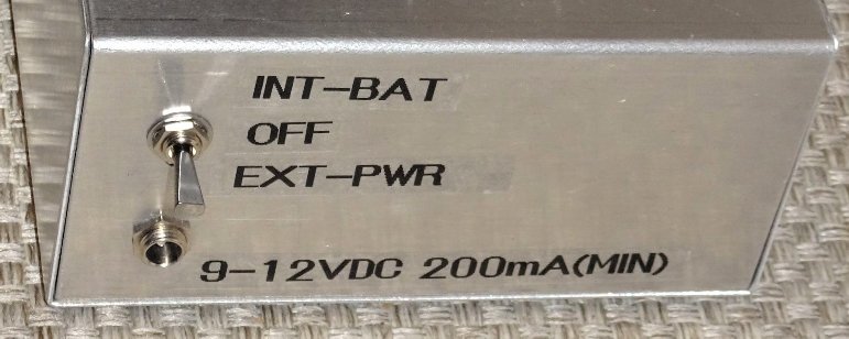
9V battery pack. Just north of that, on the back wall of the enclosure, is a DPDT-CO switch, which
will be OFF when in the center position,and select either the external 9-10V supply, or the
internal battery pack. See image below.
If running on internal battery, be aware that with sense leads open, current consumption is about 25-35 mA.
Most of that is for the DPM. Then, during measurement, the constant current source will add another
100 mA (totaling 125-135 mA). Batteries will not last long (4-6 Hours for a 9V 6xAA pack), so TURN
OFF when not in actual use.
In this construction instance, each of two kelvin probes were formed using equal lengths (about 2 feet each)
of AWG 18 wire, twisted together. For this project, we ordered a set of solderable kelvin-type
alligator clips on eBay: similar to this one. Each probe gets 2 wires. We solder one wire to one side,
and the other to the other side. When they clamp together, the two wires connect. You can get prefab sets of
kelvin clips, too. A suitable one available from Amazon (AST Labs) is ASIN B01H4GZP8E. Just don't
be tempted to use the banana plugs - chop those off and solder wires directly.
At the milliOhmmeter board end, the two kelvin probes connect as follows:
   - Probe #1: One wire to Current Source 'Pos', Other wire to 'Sense +'
   - Probe #2: One wire to Current Source 'Neg', Other wire to 'Sense -'
Thus connected, the kelvin probe (needles) deliver the exact 100mA from the current source (to the
For calibration of the MilliOhmmeter board, choose your best (most accurate)
Digital Volt Meter (DVM). The calibration will only ever be LESS ACCURATE than the calibration
equipment you use. I use a DVM with +/-0.1% DC accuracy, and if I'm really careful, I can probably
achieve calibration of +/-0.2% or just a smidgeon better.
The milliOhmmeter board (Barbouri v1.5) has two trimpots. For the '0' calibration, you'll observe
the front panel DPM. Apply power. Let it warm up / stabilize for a minute or so. Short the Sense
Inputs (+ sense -) and adjust the "zero adjust" trimpot for best '0.0000'. Unshort the sense
inputs. Place your DVM in current measuring mode (usually, you have to also change one of the
probes), and place the DVM probes across the Current Source 'Pos' & 'Neg' so that current
flows through the meter. Adjust the "100mA adjust" to give a DVM reading of exactly 100.00 mA.
Note this time you'll be looking at your external DVM (not the front panel). Do this entire
procedure twice to assure you've got good calibration on the millliOhmmeter board.
Alternately, if you have your 4-wire kelvin probes already connected, and if you have a
high-precision resistor (0.1% or better) with a value in the range of 1-to-2-Ohm - let's say 1.5 Ohms -
you can place your kelvin probe (clips) firmly onto the resistor and adjust the "100mA adjust"
trimpot to give a measured (+ meter -) value of 1.5000 (using our example).
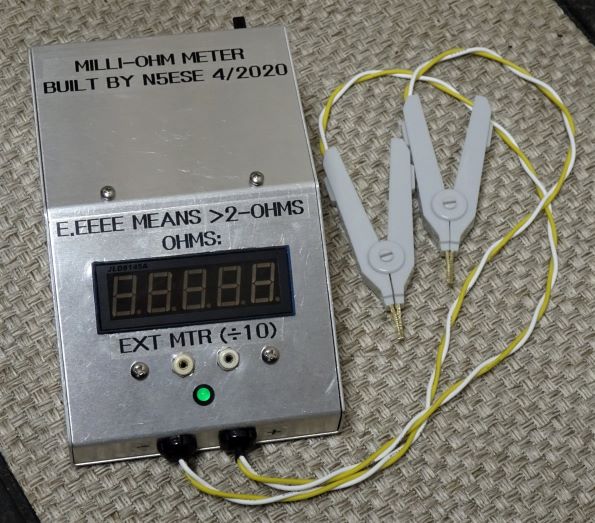
With the milliOhmmeter board calibrated, you can now make measurements.
An open circuit causes the DPM (front panel) meter to read EEEEE, as will any reading
over 1.9999 (the overvoltage behavior of different meters can vary). The milliOhmmeter board
itself is capable of driving to 4.500 Ohms, but if your DPM only goes to 2 Volts, then you can only
read to 1.9999 Ohms. This is fine - it's what we expected.
If you are tempted to use connectors inline with your Kelvin probes, don't! Just wire and solder
joints from clip to board. If the kelvin clip itself has a screw, take the screw out and discard it.
Then solder your wire to the former screw hole. When it comes to low-ohm measurements, it's best
to avoid any kind of connector, and soldering joints from clip tip all the way back to the milliOhmmeter
board is the best solution.
I don't use this very often - a few times a year - but it's very good at sorting low-ohms resistors.
73,
Monty N5ESE
dit dididit dit