N5ESE's Shielded-Loop Receiving Antenna
by Monty Northrup, N5ESE
by Monty Northrup, N5ESE
| NOTE: 'N5FC' is my former call. This project was constructed while that call was valid, and you may observe references to it. |
| Antenna Disclaimer |
| Right from the top of this page, I'm going to say that I'm an antenna experimenter, not an antenna expert. Purely seat-of-the-pants. In fact, you might even say I'm an antenna cynic. I know how to use antenna analysis tools, and I often do, but I take them with a serious grain of salt. I've found, in my 35 years of experimenting, that some antennas work much better than predicted, and some work much worse (and that they're more likely to work worse than better HI HI ). Still, I find experimenting to be one of those true joys of amateur radio, and I encourage all of you to just "try it out" for yourself, and for Pete's sake, don't take my word for it (nor my explanations). I find that most technical people do this (and I am no exception): upon observing a phenomenon, we make up an explanation for why we got our observed results. We base this explanation on the current subset of knowledge that we've gained from education and experimentation and folklore, and we're not likely to look for another explanation until we have another experience which forces us to expand or revise our previous explanation. Please realize this is the case with me, also, and then enjoy the web page. If you really want to know how it works - without my ignorant rantings getting in the way of a thorough understanding - click -here- |
Refer to the links following the narratives for schematics, layout drawings, and pictures.
When I travel on business (which is way more often than I like), I like to take along a little bit of HF ham radio for those evenings when I'm stuck in the hotel room. In 1998 I built the Jade Products SLR-40 receiver kit, so that I could have something that fit easily in my suitcase. The SLR-40 is a 40-Meter direct-conversion receiver with balanced antenna inputs, and was specifically designed for use with a shielded loop antenna.
Shielded-Loop antennas have some nice properties that make them desirable as portable receiving antennas. Because the "E-field" is electrostatically shielded, it tends to pick up less man-made noise than wire antennas. The difference in hash noise can be quite significant in metropolitan areas (and hotels have lots of hash noise). Also, (and I think this is because of its small size), it tends to pick up less local storm-related noise. An additional feature is that noise can be nulled to some extent, by turning the antenna (its null is perpendicular to the plane of the loop). Lastly, its small size lends itself to portability. (My version fits nicely in a small suitcase, along with the receiver).
Of course, the small size is a disadvantage also. Because the profile is so low, it intercepts less energy than a larger antenna. The receiver, therefore, must have adequate "excess" sensitivity and noise figure to compensate, or a preamp needs to be added. The SLR-40 receiver had more than adequate gain for this purpose, and most receivers on the 160, 80 and 40 meter bands will, because the natural and manmade noise on those bands is fairly high anyway. Another complication with small loop antennas is impedance matching, although because we are using this in a receiving application, the losses resulting can usually be ignored (i.e., overcome by receiver gain). Small loop antennas have very low feedpoint impedances, typically 5 ohms or less. For best efficiency, then, an impedance transformer is warranted (although I find it completely unnecessary with the SLR-40 receiver).
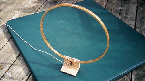
The antenna described here was an attempt to replace the antenna provided with the SLR-40, which had rather mediocre noise performance (in spite of Jade Electronics' claims), and was somewhat flimsy. One day while following my wife around Hobby Lobby (a crafts store), I noticed the wood embroidery rings, usually available in 12", 15", 18", and 24" diameters. These consist of an inner hoop of wood about 1/2-inch wide and 1/4-inch thick, perfectly circular, and an outer hoop that is cut at one point, but still circular. The outer hoop fits over the inner hoop, and a screw-fastener arrangement on the outer hoop allows it to be tightened down on the inner hoop. This looked an awful lot like a loop antenna to my eyes, and so I bought two, a 15" and 18" version. (Cost, <$12). In the same crafts store, I also found a supply of adhesive-backed copper tape, and I bought one pack of 1/4-inch wide, and one of 3/8-inch wide tape. (Cost, <$6/roll). The copper tape turned out to be a few mils thick, very strong, easy to work with, and readily solderable.
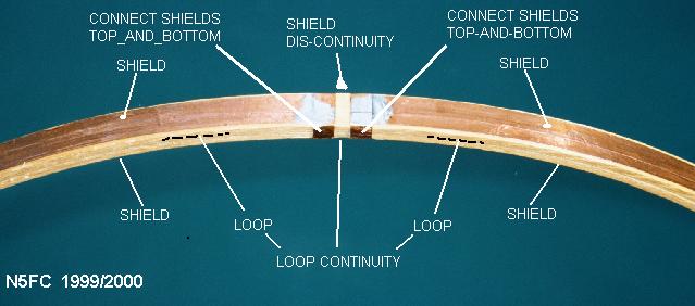
Given these materials, I decided to construct the antenna as follows: First, I carefully placed a length of 1/4-inch wide copper tape all the way around the outside of the inner hoop, centering it between the edges. The adhesive back tape stays in place easily. This will form the actual receiving antenna loop. Rather than making it continuous, the tape was folded out (perpendicularly) at each end, forming pigtails that would later be connected (by soldering) to the tank circuit at the bottom of the antenna. Second, I placed a length of the wider 3/8- inch copper tape all the way around the inside of the inner hoop, overlapping slightly, making it continuous (and soldering it lightly to make sure). Lastly, I placed more 3/8-inch copper tape around the outide of the outer hoop, up to the point where it met the screw-fastening device. Now, the hoops are assembled, aligning the pigtails-end of the inner hoop with the fastener end of the outer hoop, and tightening. We will not disassemble the hoops from this point forward. At this point, the inner receiving loop should be effectively "shielded" by the inner and outer copper tapes, but with NO continuity to either shield.
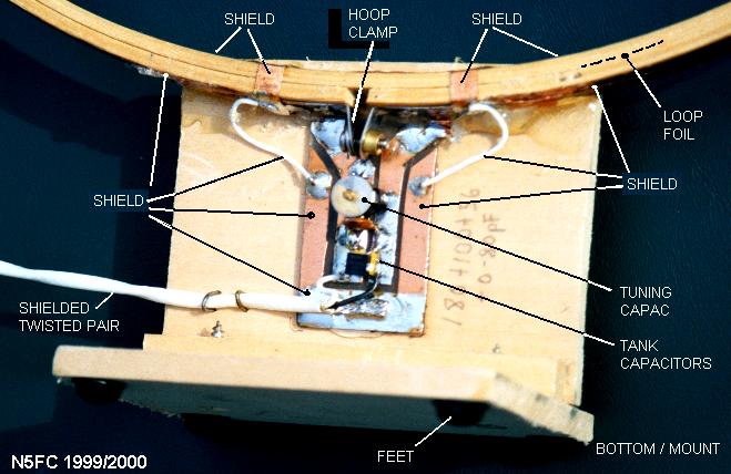
Continuing with assembly, we now cut the inner and outer copper shields at the top of the hoops (exactly opposite the fastener and pigtails), and wrap some copper tape all the way around, soldering it to the inner and outer shields on both sides of the gap. This gap is very important in creating a faraday shield that attenuates only the E-fields. Refer to the photo if this is unclear. We also wrap some copper tape all the way around, connecting the inner and outer shields, near the bottom (feed point), just outboard of the loop antenna's pigtails (and solder it). Be very careful not to short the shield to the loop antenna or its pigtails. There will be a gap at the outer shield at the bottom (due to the fastener arrangement, but none on the inner shield. If you want, you can solder the outer shield to the fastener, although this is a minor point. This can be seen in another photo..
I elected to hand-cut and hand-route a small 1 x 1-1/2-inch PCB from some scrap double-sided material I had. This would help me mount the tank components, used to resonate the loop antenna at the band of interest. I tack soldered a 8-80 pF air variable (Sprague-Goodman GZC80000, available from Digikey and others) to the PCB, and added other ceramic disk capacitors as necessary to resonate the antenna at the frequency of interest (in this case, 40 Meters) with the variable at mid-range. The pigtails of the loop connect in parallel with the capacitors, soldered to the PCB. Again, be careful not to short the loop antenna to the shield, or the antenna will not perform correctly.
We constructed a base for the antenna out of some 1/4-inch thick hobby wood (basswood, I think), purchased from the same crafts store. The pictures will show the details of this, which are quite non-critical. The hoop assembly and PCB were fastened to the mount using liberal amounts of hot-glue. We placed rubber feet on the very bottom. There may be sturdier methods of assembly, although this method has survived a dozen trips or so (so far) in a small suitcase transported through the airlines.
The antenna is balanced, and this balance must be maintained in order for the low-noise performance to be realized. This means that the receiver should have balanced inputs (as does the SLR-40 receiver), or that it be link-coupled, or that a balun/tranformer be used at the antenna. As a result of this requirement, the antenna must either be fed with two equal-length pieces of coax (shield common), or fed with shielded-twisted-pair cable. I had access to some scrap teflon-coated shielded-twisted pair, so I used that. ( I tried it earlier with two sections of coax, with equal results). In either case, the inner conductors should connect across the tank circuit/feedpoint, and the feedline shield(s) should connect to the loop antenna shields on one end, and the receiver chassis/electrical ground at the other. In our case (for use with the SLR-40 receiver), the feedline was terminated with two RCA-type phono plugs, one for each center conductor.
In the future, I plan to try other arrangements. One will be for unbalanced receivers, using a broadband RF transformer or balun mounted at the antenna to provide the balance-to-unbalanced conversion, and to provide better impedance matching (step-up-step-down). Another arrangement will insert an FET preamp at the feedpoint, powered by a 9-Volt battery, to boost the signal for use with unbalanced receivers or higher-frequency bands where the sensitivity is required. Both concepts are shown schematically below, as are other drawings and photographs of the antenna.