N5ESE's 1:4 Current Balun

(click on any picture to see larger version)
(click on any picture to see larger version)
| NOTE: 'N5FC' is my former call. This project was constructed while that call was valid, and you may observe references to it. |
Here's yet another handy little Altoids QRP project. This makes a great travel companion to the 1:1 current balun (described -here-), and is intended to aid in tuning a balanced antenna or feedline that has a high impedance (100-600 ohms). I've even used it successfully to tune a 20 meter, 1/2-wave vertical with 4 radials, placing it directly at the bottom feedpoint of the vertical, feeding it with 50-ohm line (RG-58), and letting my Elecraft K1's automatic antenna tuner do the rest.
The classic 1:4 current balun's circuit looks like so:
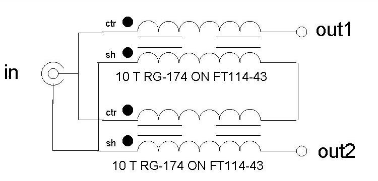
This version, shown below, is wound with 10 turns of RG-174 mini-coax on each of two FT114-43 ferrite cores.

Measurements using my MFJ Antenna Analyzer showed that the SWR rose gradually from 1.1:1 at 21 MHz to 1.25:1 at 30 MHz (into a 200-ohm dummy load).
For a close-up view of the toroid windings and connections on this version, click -here-
Construction-wise, an isolated BNC is used at the input (Amphenol 31-010), though a garden variety BNC connector (non-isolated) mounted directly to the Altoids box could as easily been used. I grabbed a piece of 3/32" thick PC board that I had laying around as scrap, peeled off most of the copper, but left some copper traces to ease wiring. The PCB would also serve as the "mounting plate", mounting the completed toroids with hot glue. To preserve balance, attention is given to keeping all lead lengths symmetrical; that is, all the leads on toroid 1 are identical to toroid 2, and the length of the wire from any junction to the input and the output connectors, is identical for both toroids. Standard banana plug binding posts were used for connecting the feedline to the balun's output. It is assumed that the transceiver or antenna tuner will be earth-grounded, to provide a path for bleeding static charges on the antenna.
In operation, a female-to-female BNC adapter is mounted on the BNC jack of the balun, and the balun is then mounted directly onto the BNC jack on the rear of the transceiver or antenna tuner. Alternatively, mount the balun at the feedpoint (assuming the feedpoint is 100-400 ohms), and feed using a half-wavelength of coax. While throughput losses were not measured, it can be assumed that the balun will be lossy for impedances much above or below the intended matching range (100-600 ohms), or outside the intended frequency range (1-30 MHz). Also, I believe the balun is readily usable at 10 watts applied power, but that it may be good to somewhat higher levels. Use at higher levels has not been analyzed nor tested.
I used this balun between my K1 and 1/2-wave vertical to help match the antenna. Without it, the K1's automatic antenna tuner could not find a match below 5:1. With the 1:4 step-up balun, the K1 managed a 1:1 match, and 30 QRP contacts were made in dreadful band conditions during the 2002 Flight-of-the-Bumblebees contest, with contacts up and down both coasts. Needless to say, this balun is a keeper.
To see a 1:1 current balun, go -here-
73,
monty N5ESE