N5ESE's Free-Standing Antenna Frame
(click on any picture to see larger version)
(click on any picture to see larger version)
| NOTE: 'N5FC' is my former call. This project was constructed while that call was valid, and you may observe references to it. |
|
Quick Note: The DK9SQ Telescoping Fiberglass Mast, as far as I can see, is no longer available. But there are lots of FG Mast manufacturers out there, with equivalent or near-equivalent masts. Try: MFJ Enterprises (search on "telescoping") Sotabeams (UK) (look for antenna supports) Max-Gain (look for push-up masts) |
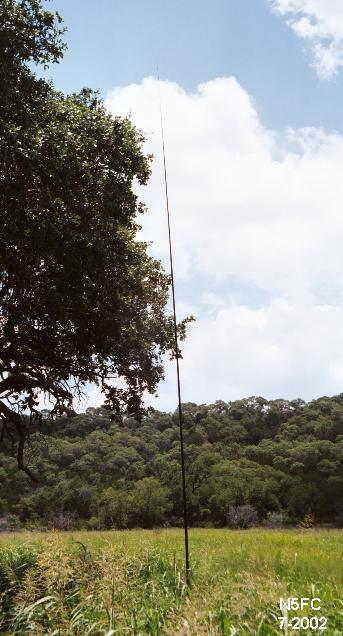
Trees in the hill country west of Austin tend to be "puny", growing to only 20 or 25 feet, so I recently purchased a 32 foot DK9SQ telescoping fiberglas mast (available from Kanga US) to get the antenna above the treetops (or bush-tops, as the case may be). One of the things I noticed in central Texas, as I tool around the countryside looking for a neat spot to operate QRP portable, is that finding a tie-off point for a portable mast (or sometimes, just finding a crack in the rocky soil to pound in a tent stake) is sometimes a challenge.
This page presents the construction details for a free-standing antenna frame, designed to support the DK9SQ mast (or the MFJ Enterprises mast, of similar construction). The total weight of the frame is 8-1/2 pounds, a good match for the 4-1/2 pounds of the mast. The frame is compact, and breaks down almost entirely into pieces 3 feet or less in length, making it quite compact for traveling and carrying. Here's a picture of all the parts, spread on the floor prior to packing:
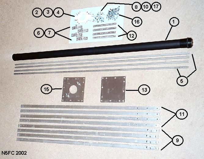
No, I didn't paint those numbers on the floor with magic-marker - boy, would I be in the doghouse for a long time - we'll use the index numbers later.
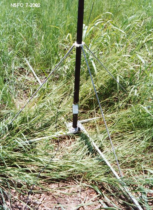
I pack mine into the canvas bag that came with my 6-1/2 pound, $20 aluminum/canvas folding chair, and keep it in the trunk of my car, along with the mast and QRP field kit. The picture at the top of this page depicts the mast setup at the destination of a four-mile hike to operate in the "Flight of the Bumblebees" contest, during which I carried a small backpack with the K1 and accessories, the chair and frame in the canvas bag, and the DK9SQ mast in it's cloth bag. Setup takes 15-20 minutes, and the mast was seen to be unconditionally stable with wind gusts of 20-25 mph (higher winds have not been encountered).
The frame is mainly made of aluminum stock. When assembled, it forms a steady base, into which the bottom of the mast may be securely locked in place. Four horizontal legs arranged at right angles, attached to a small, central base plate form mechanical ground-contact for the frame. Each leg is about 6 feet long, making the base footprint a substantial 11-1/2 feet diagonally. Four lightweight struts quickly and easily attach near the center of the four horizontal legs, then join to a custom clamp about 3 feet up from the base of the mast. The clamp is a two-piece semicircular affair made from strong, thick ABS plastic, which gently but firmly grips the mast without crushing it. Once deployed, the frame is extremely stable, but light enough to pick-up and re-position with one hand. Forces (usually caused by wind) applied to the exposed mast, tend to be transmitted downward into the struts, then through the struts to the middle-point of the extended legs. During field deployment, we observed the tip of the mast swaying 2-3 feet during wind gusts, yet the bottom of the mast and its frame never budged even a fraction of an inch.
Sometimes a picture is worth more than a thousand words, and such is certainly the case with this contraption. So let's tell the story in pictures. Later, we'll present dimensioned drawings of the piece parts, and pictures from the field.
Here's a picture of our first assembly, accomplished in the family room (with the YF chuckling softly in the background).
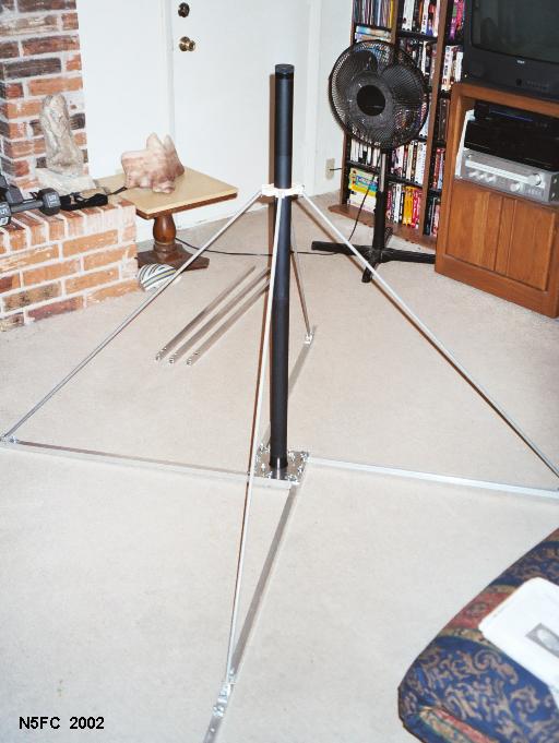
Only half the horizontal legs can be seen (i.e., the inner legs)... there simply wasn't room to assemble the outer legs. One outer leg (the one "comin' at ya") is installed, but you can only see a few inches of it, though it extends another 3 feet toward you. Notice the four aluminum tubing struts, and where they connect to the horizontal legs about 3 feet from the base plate, and where they connect to the special clamp, about 3 feet up the mast. We'll look at more details of these soon.
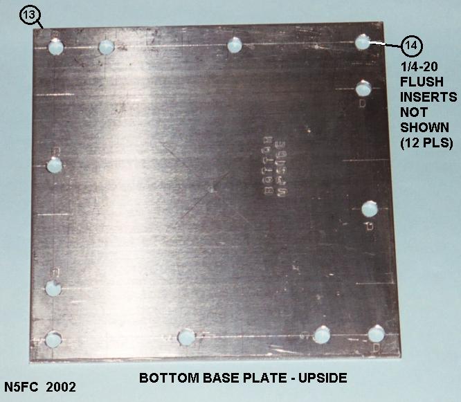
Here's a closer look at the base and base-plate assembly:
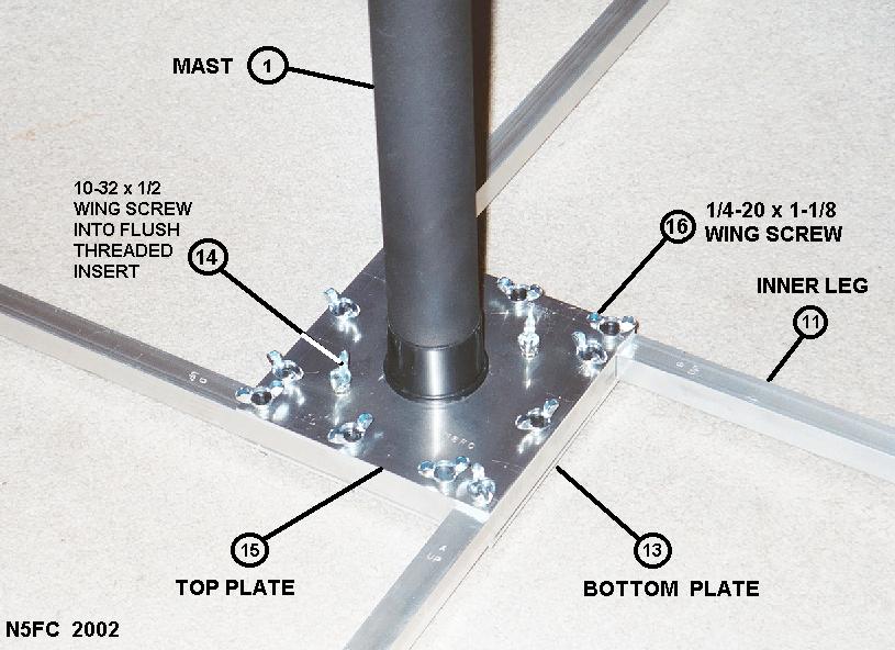
Several key details will be noted in the above picture. The horizontal legs are captured and held in place between two 6x6 inch heavy aluminum plates, sandwich-style. All assembly is done using wing-headed screws, to minimize the need for hand tools. In the center of the top baseplate, we cut a 2" diameter hole (but not in the bottom baseplate). The DK9SQ mast has a screw-on cap at the bottom; unscrewing it reveals a length of threaded mast, which fits cleanly into our 2-inch hole. Screwing the cap back on captures the mast to the top plate. [By the way - I can hear the gears turning - the mast threads themselves are nowhere nearly strong enough to support the mast, so don't even think about it.] Each horizontal leg gets three screws going all the way through. I mounted threaded-inserts in the bottom plate to receive the screws... that way I don't have to carry (and lose) nuts. I stamped each metal piece with an index letter, so that I could easily remember the assembly order. You'll also see two additional wing-screws, mounted to the top plate. These are placed to afford electrical ground points, should you want to use them. The frame comprises four six-foot radials, and you can use the ground points to attach additional radials and your coax feedline's shield, if desired.
By the way, you may be wondering about the circled numbers. These will index to the overall assembly drawing, and the parts list, to be presented later. You'll see these in a lot of the drawings and pictures.
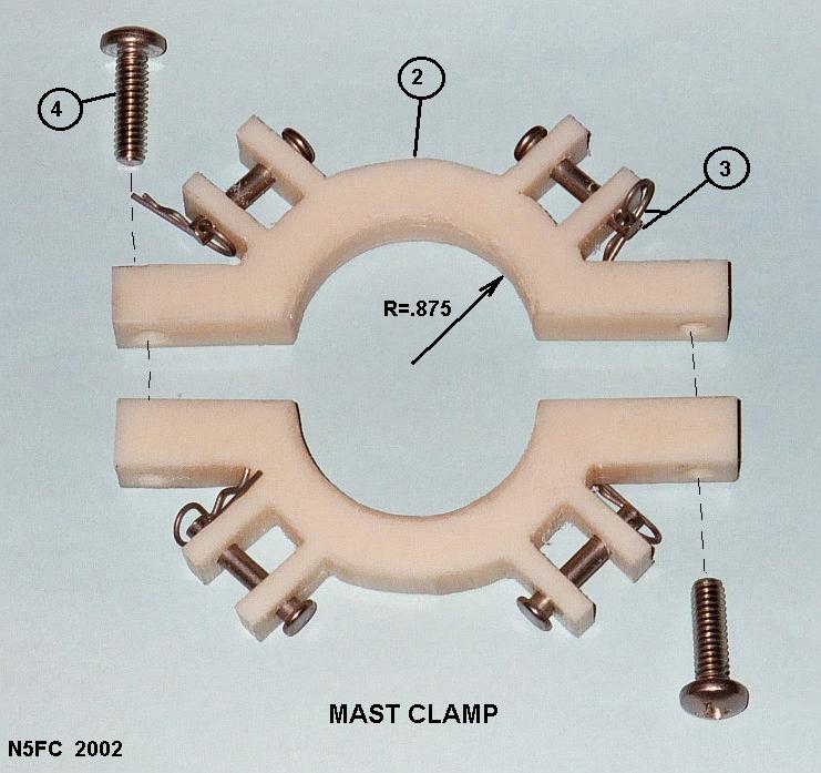
Let's look at the mast-clamp assembly next:
(click on the picture to see larger version)
The clamp assembly is made up of two identical halves. It looks complicated, doesn't it? This piece would cost a fortune to have commercially fabricated in a machine shop, but we're not nearly so picky... plus, we don't have a fortune. I selected ABS plastic for the material. It's extremely strong, and drills, taps, and machines well. I printed the drawing of the half-clamp to X1 scale, then scribed the shape onto the 3" wide x 1/2" thick ABS rectangular bar stock. [Here are two files you can use as full scale templates - Dxf - Word97 -]. Rather than machine it, I cut it carefully using a vertical band saw. This mainly takes care and patience (not skill), plus a little time with the bastard file afterwards. The picture above shows the pieces arranged approximately as they would be prior to fastening to the mast. The two screws insert through a clearance hole on one side of the clamp, and screw into tapped threads on the mating side. I'm looking for a long shouldered screw that can be hand-turned, to replace the Phillips-head screws, but I haven't found it yet. Thus far, these are the only parts of the frame that require a hand tool. The strut fits into the mounting ears (where we have drilled 3/16 holes), two in each half-clamp, and then we use a 3/16 x 1" clevis pin and matching cotter pin to hold the struts in place. Takes about 30 seconds tops to mount a strut. Assembled like so, the struts are free to swivel during frame assembly operations.
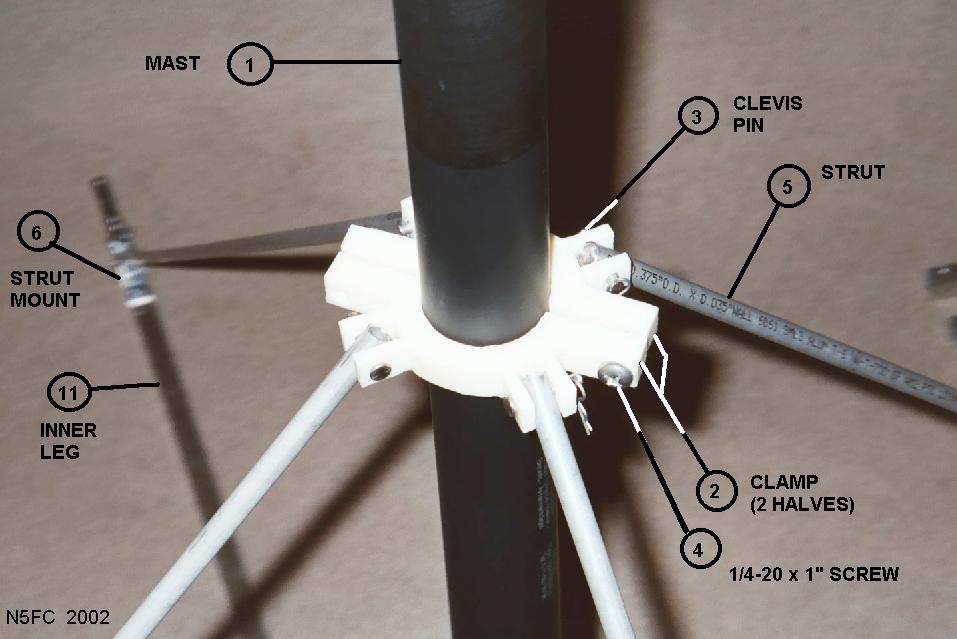
Here's an image of the clamp assembly mounted to the mast, with struts attached. Notice how the struts are mounted using clevis pins and cotters, and how the clamp grips the mast evenly and solidly:
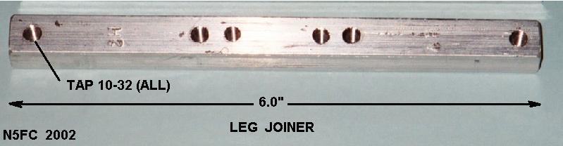
Before we look at how the struts mount on the other side, there are two piece parts we need to understand first. Understanding these will allow us to understand how the 3-foot inner leg and 3-foot outer leg join to form a 6-foot leg. The key part is shown below:
(click on the picture to see larger version)
We call the above part a "joiner bar" (clever, ain't we?). The joiner, which is threaded to accept six 10-32 screws, inserts halfway into the square tubing of the inner leg, and halfway into the outer. Again, we'll use wing-screws to fasten the legs to the joiner. But before we fasten the inner leg, we'll mount an additional piece:
(click on the picture to see larger version)
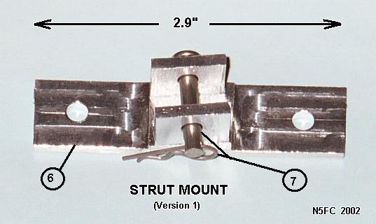
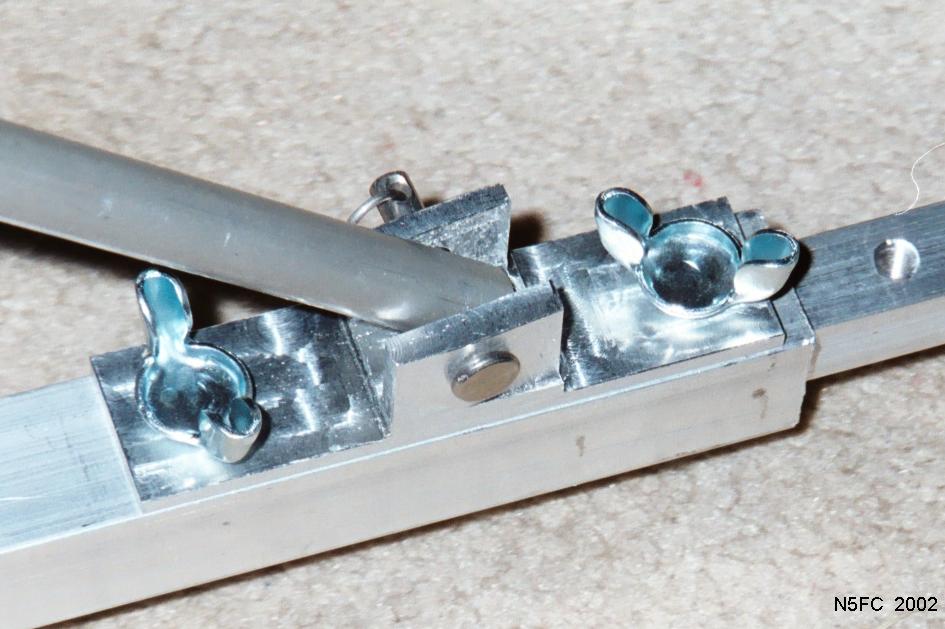
We call the above piece the "strut mount". Don't be put off by it's complexity. We originally machined this on an end mill, and then thought of a simpler way to accomplish the same thing. Using the new drawing, and a lot of care and patience, one should be able to fabricate a similar piece using a vertical band saw. CAUTION! Don't even think about fabricating this piece (or the clamp) using anything except a vertical band saw or a milling machine. The result is bound to be disastrous for the piece, and will likely result in injury to the "machinist". DON'T DO IT! The strut mount fastens to the inner leg, near the joint between the inner and outer leg, using two wing screws into the joiner bar (internal to the leg). Make sense? Here's a picture of the strut, inner and outer legs, and the strut mount, all assembled; the joiner bar is hidden inside the joint:
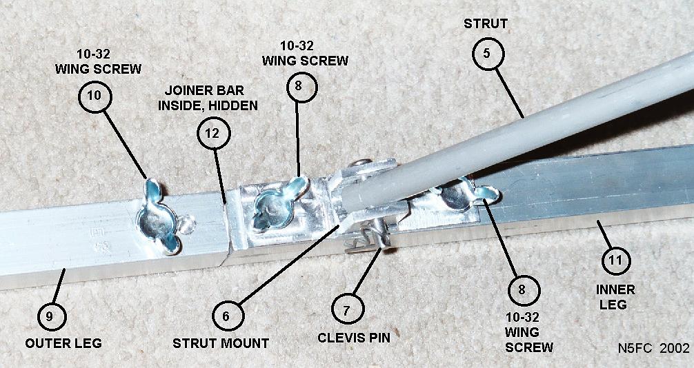
An even closer picture of the assembled strut mount can be seen -here-.
The end of the outer leg has a 3/8" hole for general utility purposes. If you don't trust the struts and legs to fully support the antenna, or if you anticipate really high wind gust, or if you have a little too much "wind load" in your antenna, you can use round aluminum tent pegs to help secure the frame into the ground.
Notice that each part is indexed by a letter (circled). These correspond to index numbers in the parts table, below. Also, where a picture of the part exists, click on that part's name (in the table, below) to view the picture. Fabricated parts contain a link to the mechanical drawing in the NOTES column.
| INDEX # | QTY | NOUN | SOURCE | PART NO | NOTES |
| 1 | 1 | DK9SQ Mast | Kanga US | dimensions | |
| 2 | 2 | Half Clamp, ABS | McMaster-Carr | 8712K59 | Fab from ABS stock, see dwg |
| 3 | 4 | Clevis/Cotter Pin Set, 3/16"Dx1"L | McMaster-Carr | 92390A821 | 5/pk |
| 4 | 2 | Screw, Pan, SS, 1/4-20x1-1/4" | McMaster-Carr | ||
| 5 | 4 | Strut, 6061 Alum Tubing, 3/8"ODx0.035"TH | McMaster-Carr | 89965K45 | Fab from tubing, see dwg |
| 6 | 4 | Strut Mount, 2024 Alum rect bar, 1-1/2"Wx3/4"TH | McMaster-Carr | 89215K317 | fab from rect stock, see dwg |
| 7 | 4 | Clevis/Cotter Pin Set, 3/16"Dx1"L | Same as Index 3, above | ||
| 8 | 8 | Screw, Winghead,10-32x1/2" | McMaster-Carr | 91510A124 | 20/pk |
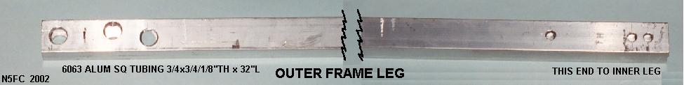
| 9 | 4 | Outer Frame Leg, 6063 SQ Tubing, 3/4x3/4"x1/8"TH | McMaster-Carr | 88875K31 | fab from alum stock, see dwg |
| 10 | 8 | Screw, Winghead,10-32x1/2" | Same as Index 8, above | ||
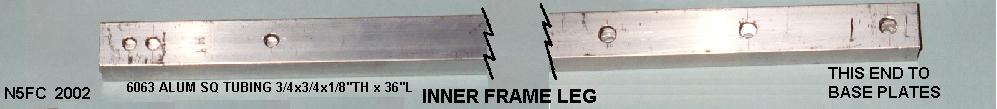
| 11 | 4 | Inner Frame Leg, 6063 SQ Tubing, 3/4x3/4"x1/8"TH | Same as Index 9, above | fab from alum stock, see dwg | |
| 12 | 4 | Joiner Bar, 6061 Alum SQ Bar, 1/2x1/2" | McMaster-Carr | 9008K23 | fab from alum bar, see dwg |
| 13 | 1 | Bottom Plate, 5052 Alum, 6x6x1/8"TH | McMaster-Carr | 88895K1 | fab from alum plate, see dwg |
| 14 | 12 | Nut Insert, Flush Mount, 1/4-20 | McMaster-Carr | 94674A533 | pk/25 |
| 15 | 1 | Top Plate, 5052 Alum, 6x6x1/8"TH | Same as Index 13, above | fab from alum plate, see dwg | |
| 16 | 12 | Screw, Winghead,1-4-20x1-1/2" | McMaster-Carr | 91510A160 | pk/10; cut to length, 1-1/8" typ |
| 17 | 2 | Nut Insert, Flush Mount, 10-32 | McMaster-Carr | 94674A528 | pk/25 |
| 18 | 2 | Screw, Winghead,10-32x1/2" | for top plate, same as Index 8, above |


Here's an interesting aside regarding the DK9SQ mast. I originally wrapped the 33 foot wire loosely around the mast, so that my "vertical" would not be flopping around in the wind. Big mistake. Turns out the black graphite (or whatever) in the fiberglas rod is quite RF absorbent. On 20 and 15 meters, I could see a 2-3 S-unit decrease in received signal strength with the wire wrapped around the pole. And I wasn't getting out well at all, getting S2 signal reports from my Elecraft K1. But angled away from the pole (with the wire unwrapped and about 3 feet at the bottom), everything was hunky-dorey. Now I'm suddenly getting S7 reports... much better. It took me about 2-1/2 hours to realize what was going on.
By the way, I'd love for someone knowledgable in mechanics to do a wind-load analyses for this frame, based on the telescoping mast, and a typical portable vertical, dipole, or loop antenna. Such an analyses is way beyond my training and skills.
Let me know what improvements you make...
73,
monty N5ESE