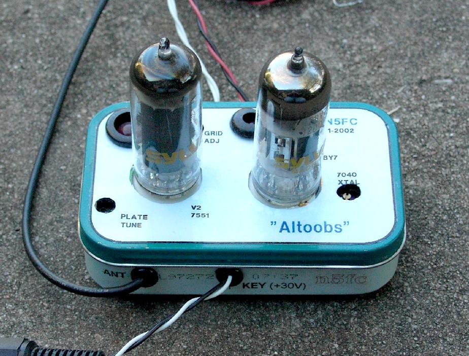
"Altoobs"
2-Tube 40 Meter CW Transmitter
(click on any picture to see larger version)
(click on any picture to see larger version)
| NOTE: 'N5FC' is my former call. This project was constructed while that call was valid, and you may observe references to it. |
My homebrew projects tend to progress in stages, spread over time. This one was certainly an example of that process. Being enamored of projects built into the ubiquitous Altoids tin, I decided I wanted to see if I could package a two-tube crystal-controlled transmitter onto one of these boxes. I began thinking about it about 3 years prior, sketched out a paper design six months later, acquired tubes about a year ago, and finally put solder to it last month. I decided to name it "Altoobs", a play on the tradename "Altoids".
As you can see from the schematic below, there is nothing unique about the circuitry in this two-tube 40-Mter crystal-controlled transmitter. In fact, it's fairly "cookbook", using a pentode-based colpitts crystal oscillator, followed by a beam-power-pentode final amplifier with pi-output network, all cathode-keyed.
(click on above image to see larger image with component details)
We selected a 12BY7 as the oscillator tube. The functional characteristics of the 9-pin miniature 12BY7 are nearly identical to the old metal 6AG7 which was popularly used as a crystal oscillator in 50's and 60's novice transmitters. To keep things small, we use a 7.040 MHz crystal in a modern HC-49 holder. This was also the reason we used a separate oscillator and amplifier. The oscillator would not have to run so much current (to deliver power to an antenna load), and so we stand less chance of damaging our crystal (modern crystals are smaller and more susceptable to damage by excess current than ye oldf FT-243's).
We departed conventional wisdom in selecting a final amplifier, because almost all the popularly-used tubes required plate and screen voltages of 250 V or more (usually. more). The 7551 was a special-purpose VHF class-C amplifier tube, most often used in industrial/police service in commercial mobile radio gear in the 60's. Packaged in a 9-pin minature tube, it was capable of 10 watts output at 30 MHz, with 250 V plate supply, and has a 12.6 V filament. [FWIW, the 7558 is an identical tube with 6.3 V filament, and can do the same job]. We designed our output circuit for a plate impedance of 3000-ohms, transforming 3000-ohms to 50 at the antenna port. At 150 Volts of B+, then, we might expect a plate current of about 25 mA, and a DC power input of 3.75 watts, nominally. With a projected efficiency of 60%, we should manage something around 2 watts output. The 7551 is not actally characterized for operation at less than 250 V plate and screen, but it's plate curves show significant plate current at 150 Volts and lower, so we will assume it will do something useful with a 150 Volt supply. By the way, we could get a full QRP gallon (5 watts) by running a plate voltage of 225 VDC, but we'll forego the extra power in deference to simplicity, compactness, and reduced stress on the components.
To reduce component count and eliminate one power supply voltage, we opted to use cathode keying. With a grid cutoff voltage of somewhere around 20-25 volts, and total (V1 + V2) cathode currents of less than 50 or 60 mA, we should even be able to use our modern solid-state keyer.
In order to package all this circuitry (sans the tubes) into an Altoids box, we needed to deviate from traditional tube construction protocols. First, we decided to use toroid cores instead of air-wound coils in all tuned circuits, as air-wound coils are just too big. And instead of the classic pi-net with variable capacitors for tuning and loading, we decided on a fixed-loaded pi-net, designed to load a 50-ohm antenna. This is quite reasonable in this day and time when almost all solid-state rigs are designed for fixed 50-ohm outputs. If we need further matching, we'll accomplish that with an external antenna tuner. In lieu of meters for plate current indicators, we decided to try LEDs, which are considerably more compact. Finally, in an effort to keep components small, we'll plan for a plate voltage of 150 V. This means we can use regular 1/4 watt resistors, and small-package capacitors. The lower B+ voltage means our final won't put out quite as much power as the tube is capable of, but if we can get 2 watts out, we'll be happy. Of course, the lower plate voltage also simplifies power supply design, keeping the cost and size of that to a minimum. [You can see our power supply -here-]
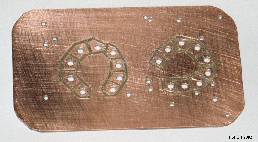
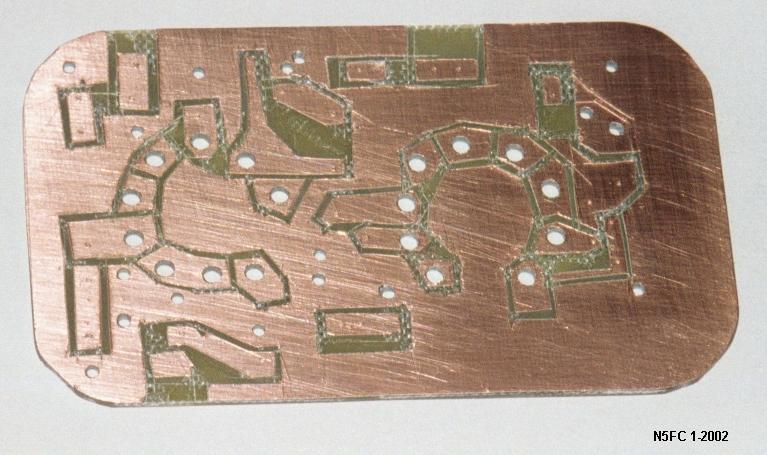
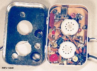
A printed circuit was used to mount circuitry. I prefer the old "cut-and-peel" method, utilizing a hobby knife to remove unwanted copper and form islands.
We used a double-sided board, cut to "just fit" inside the Altoids tin. We used the bottom side as ground plane, and drilled holes as required. We obtained pc-mount 9-pin ceramic sockets, mounting them through the board, and soldering the pins on both sides. Components were mounted "surface mount" style, on the top of the board, which is also the circuit-side. This board ain't pretty, but it does the job:
(click on either image above to see a larger version)
Below is a picture of the pcb, populated:
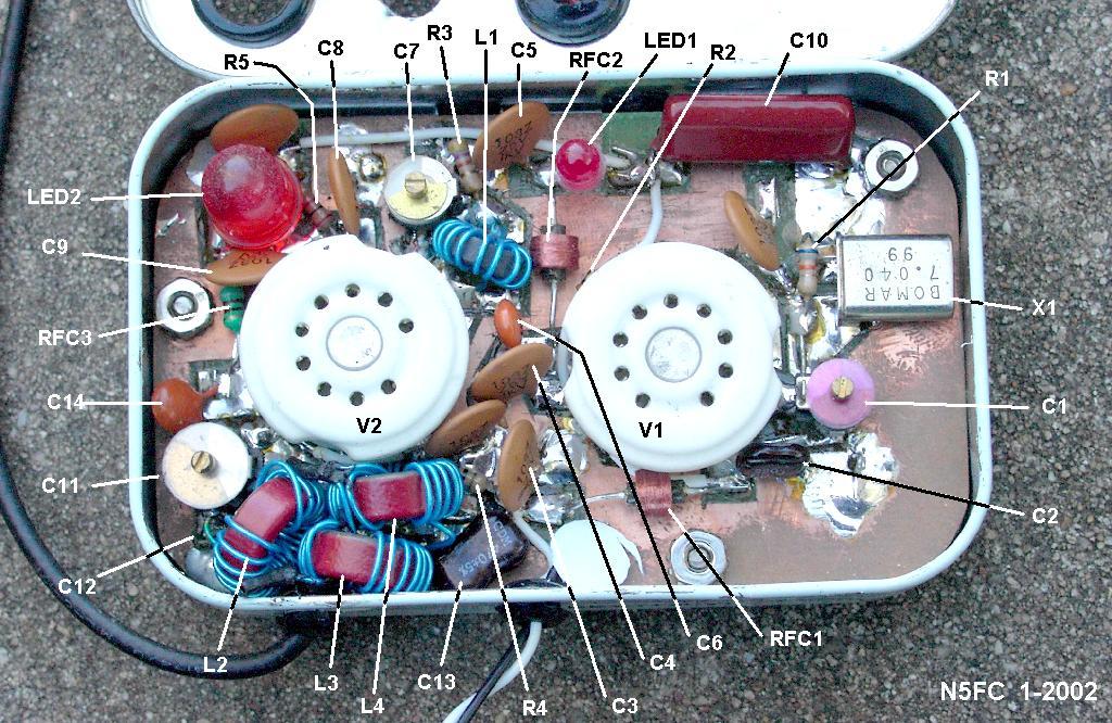
(click on the image above to see a larger, annotated version)
From the picture, you'll notice a few unusual things. The toroidal cores are wound with kynar-insulated wire-wrap wire. Enameled wire probably should not be used, because the insulation will likely breakdown between the core and the wire. Also, the large red LED, rated at 60 mA, was intended to be a plate current indicator for the final amplifier. I say intended because although it works, it's very hard to quantify the current. We kept it because it makes a cool blinking light as you key, and is a good confidence indicator for plate current. The smaller LED, rated at 20 mA, performs the same function for the plate circuit of the oscillator.
Notice that there are three variable capacitors, of the 8 mm poly-insulated trimmer type. The one nearest the crystal allows the crystal frequency to be adjusted somewhat. Adjust this one for minimum chirp and drift (there won't be much, regardless of setting).. The other two adjust the final amplifier's grid and plate tanks, respectively.
The completed pcb is mounted inside the Altoids box using three 1/4" high aluminum spacers and appropriate hardware. B+ voltage and filament voltage are brought into the box through rubber grommets in the lower back (behind the cover hinge), via pigtails that connect to binding posts on the power supply.. Shorter pigtails, terminated with an appropriate connector, provide for antenna connection and key line input. Holes are drilled in the hinged cover of the Altoids box to allow for mounting of the two tubes, for access to the trimmer capacitors, and to allow the LEDs to been seen. Here's a picture with the cover open (with an output older filter section in it):
We fabricated a label for the cover, which you can (mostly) see below:
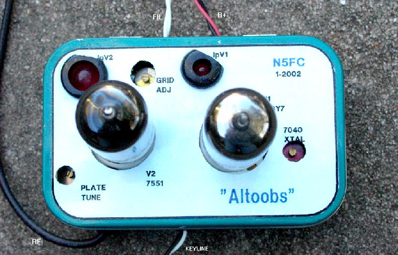
(click on the image above to see a larger, annotated version)
Below is a picture showing a complete working setup. The gray box on the left is our homebrew 145 V Regulated Power Supply, which also supplies the 12 V filament voltage. In spite of being fairly compact, the power supply, with it's two transformers, is considerably larger and heavier than the transmitter. The antenna cable, which exits the Altoobs chassis on the lower left, is connected to our homebrew dummy load. And a J-38 keys our transmitter. By the way, I was also able to directly key the Altoobs using our homebrew CMOS Keyer and the K1EL Keyboard.
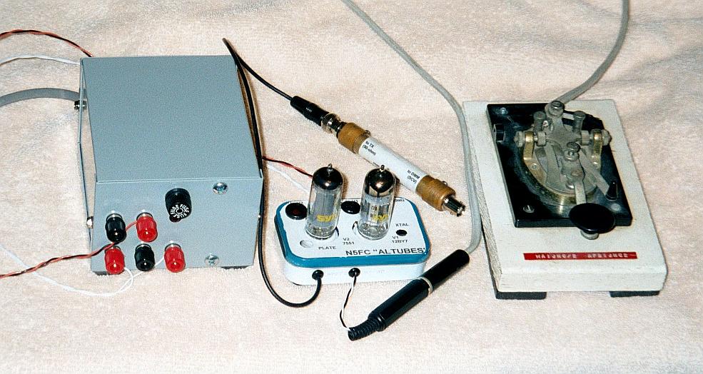
(click on the image above to see a larger, annotated version)
For those who might want to duplicate the Altoobs, please refer -here- for additional construction and tune-up notes, in an Acrobat-format (.pdf) printable file.
Our first QSO with the Altoobs, yielded a distance of 817 miles (Austin, TX to Atlanta, GA), a 549 report, and a good 35 minute ragchew with with Jim, AD4J.
Enjoy, good luck, and 73!
monty N5ESE