This describes a 0-30dB Step Attenuator (10 dB steps, i.e., 1/10 power per step) capable of 5 Watts
dissipation. It is compact and fully shielded. It can be used as any step attenuator might be
(as a piece of test
equipment), but because it can dissipate some power, it can be used inline
with a QRP transmitter to reduce the power to the antenna in 10-dB steps. So if I'm running QRP 5 Watts, I can readily step down to 0.5 Watts, 50 mW, 5mW with the flip of a switch. (so about 2 S-units at a time. I've had some memorable 2-way QRP/QRPp QSOs by using an antenuator like this.
Step attenuators are used all over the workbench for various tests, but most readily available
commercial step attenuators can only handle 1/2, 1, or (rarely) 2 watts. This will handle 5 watts CW and
10-12 watts SSB (PeP). So coupled inline with a CW or SSB QRP transmitter and antenna, it can be
used in 1 dB steps to reduce power to the antenna. How far can you QSO with 500 mW, 50 mW, or even 5 milliWatts? You might be astonished!
And a Bypass Switch is included for going direct to the antenna during receive (if needed) or when conditions change.
And this is perfect to put inline (30 dB setting, not Bypass!) to your NanoVNA for checking harmonics or filters. Your QRP transmitter will see very near 50-Ohms (1:1 SWR) and your NanoVNA will see but milliWatts. I'd put some tape on the Bypass switch to make sure it doesn't accidentally get switched to full power - YIKES!
We started with a QRPGuys 10/20/30dB Attenuator Kit. We wanted to use our own switches, and our own box, so we ordered that stuff online.
For the enclosure, we used a Hammond 1590G diecast aluminum box. It's holds the board "just
right" if you use 4 spacers to mount it. We used short wire jumpers to get the BNC's where they
need to go after the hack job.
We mounted the resistors on the same side of the board as the switches, because this box is quite shallow.
Instead of the original slide switches, we'll use a good quality 250VAC DPDT mini-toggle (Nidec
p/n 8J2011-Z) with silver contacts rated at 3A. We need 4 of them, including the Bypass switch.
We will have to solder a short bare-wire jumper at each switch terminal, as the spacing between
terminals is not quite the same as with the original slide switches.
Here are some pix (click on any picture to see larger image):
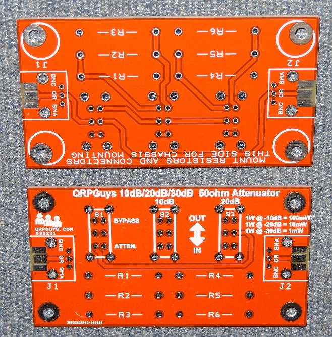 ...bare board (both sides shown)
Note: Two PCBs are shown above (so that I could show both sides, including
silkscreens). But only one PCB is needed.
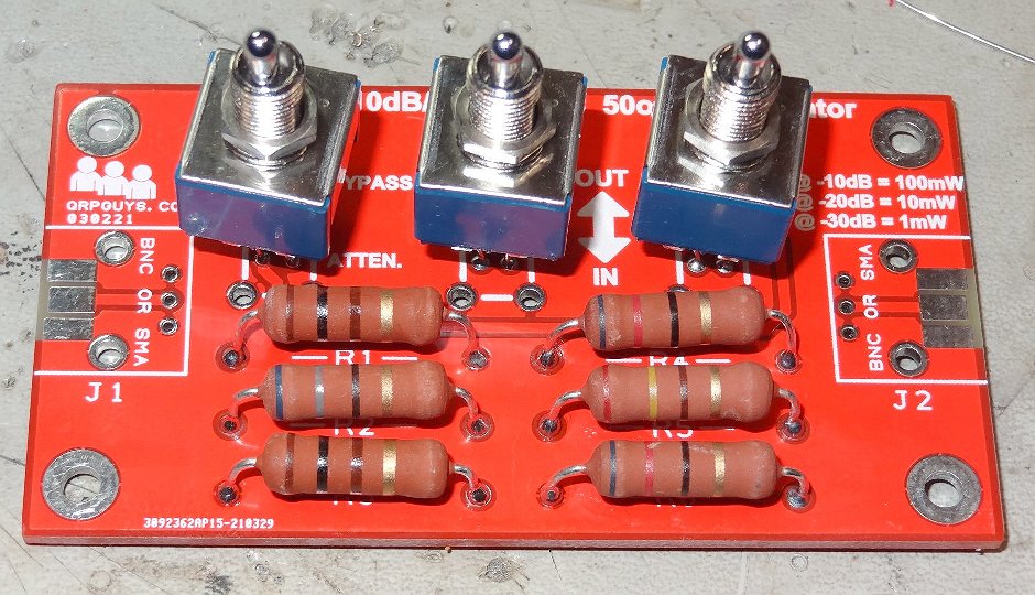 ...toggle switches and resistors
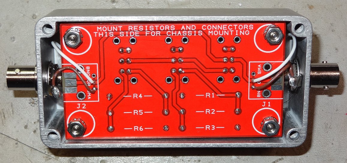 ...board/switch assembly mounted in box
We ran some tests on our little nanoVNA, focusing on the 6 Meter band as the most likely "worst case"
(the attenuator is rated to 60 MHz). Five captures below (Bypass, 0dB, 10dB, 20dB, 30dB):
_20221231.JPG) ...Bypass
...Bypass
_20221231.JPG) ...0 dB
...0 dB
_20221231.JPG) ...10 dB
...10 dB
_20221231.JPG) ...20 dB
...20 dB
_20221231.JPG) ...30 dB
...30 dB
In the above photos, the marker is at 54 MHz. Red is measured Attenuation. Yellow is SWR.
Numbers look pretty good, especially given that the resistors are MOX type at 5% tolerance.
I've used this a number of times on-the-bench and on-the-air. It does the job very nicely at QRP 5W.
73,
Monty N5ESE
dit dididit dit
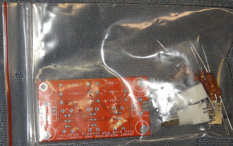 ...kit, as received
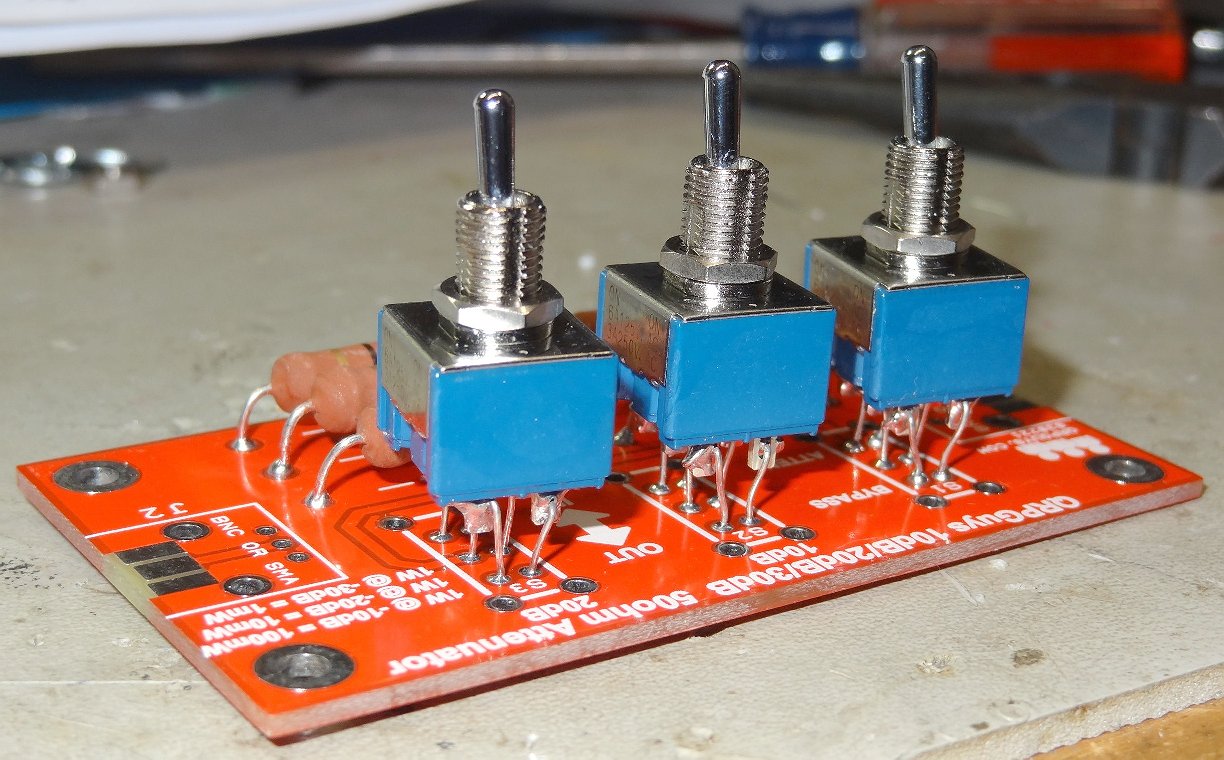 ...another view
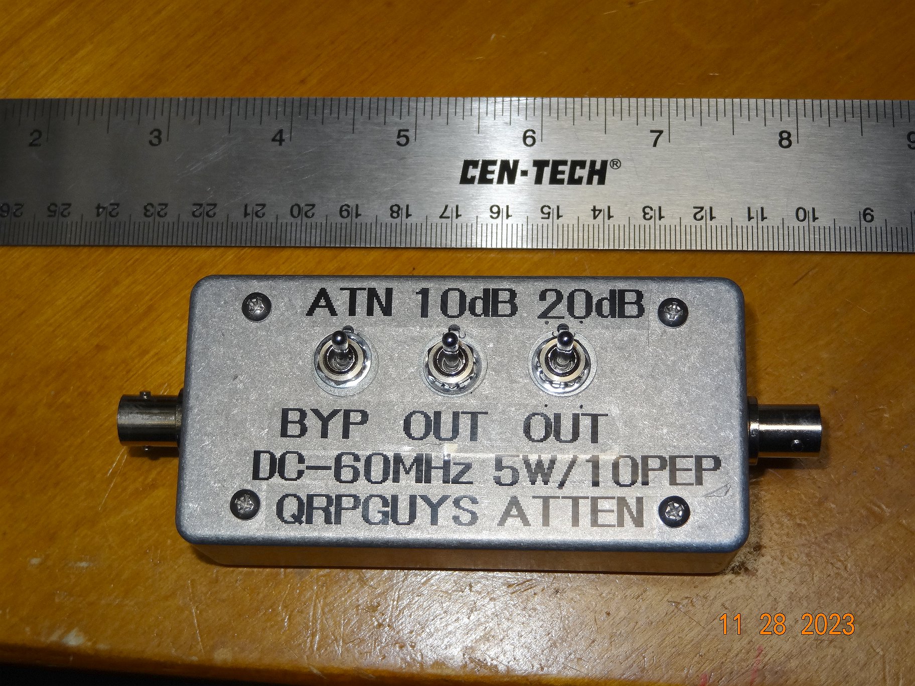
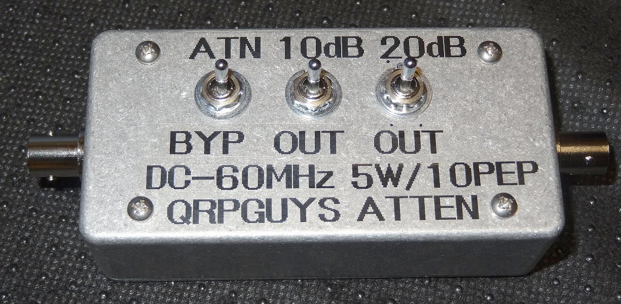 ...final, with labels